Turbine meters are used where their accuracy and rangeability are required. Their major application is for custody transfer and in-line product blending. The pulse outputs of turbine meters may be scaled for direct totalization in engineering units.
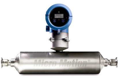
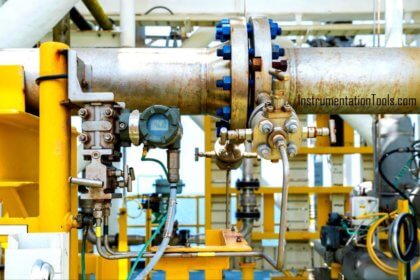
Turbine Flow Meter
Outputs from turbine meters are suitable for control or recording applications and are ideally suited for batch control applications.
Compensation for non-linearities due to viscosity is also available.
Advantages
Turbine meters have the following advantages
- Accuracy of 0.25 percent of rate with a repeatability of 0.10 percent or better is normal.
- Rangeability varies depending on meter design, fluid viscosity, density, and meter size.
- A high flow rate for a given line size is obtainable.
- Designs for very low flow rates are available.
- Turbine meters are available for a wide range of temperature and pressure ratings.
- Specially designed turbine meters are available for bidirectional flow.
Characteristics
Turbine meters are limited by the following characteristics:
- They are susceptible to wear or damage if the process stream is dirty or non-lubricating.
- They are susceptible to damage from Overspeed and pulsing flow.
- They require maintenance and may require a return to the manufacturer for recalibration after a bearing change or other maintenance.
- Their rangeability is affected by high viscosity and low density.
- Their cost is relatively high.
- They require strainers.
- Provers are required to maintain calibration accuracy.
Turbine meters are installed directly in the process line. The line should be relatively free from vibration. Meters with integrally mounted, direct-reading registers should be positioned so that they can be easily read and maintained.
Turbine meters are normally installed in horizontal lines but may be installed in vertical upflow lines. It is necessary to specify the position in which the meter is to be calibrated. Calibration for the installed position is required.
The accuracy and repeatability of measurements from turbine meters depend on the upstream and downstream piping. In addition to sufficiently long straight runs upstream and downstream, straightening vanes are required for high accuracy.
The need for bypass piping for turbine meters is determined by the application. It may be necessary to isolate or disassemble the meter for maintenance purposes.
In continuous service applications, where shutdown is considered undesirable, block and bypass valves must be provided to permit process operation while the meter is being serviced. Conditions that may necessitate disassembly of the meter include damage caused by foreign material, wear, or build-up. of solids.
If the meter is bypassed, it should be in the main run, with the line-size block valves placed beyond the meter’s required upstream and downstream piping runs. The bypass valves must be capable of positive shutoff to prevent measurement errors. The bypass piping installation should be free draining.
Bypasses are not permitted for custody transfer applications.
All turbine meter installations should have strainers to prevent damage to the meter rotor. The strainer must be capable of removing particles of a size that might damage the rotor and bearings. The strainer should be located upstream of the required meter run.
The signal from a turbine meter is a low-level pulse, which makes it especially susceptible to noise pickup. Shielding of signal wires is recommended to eliminate spurious counts. If the transmission distance is more than 10 feet (3 meters), a preamplifier is recommended. The manufacturer’s instructions should be consulted for details.
Care must be taken to prevent damage to the turbine meter at the initial start-up. The meter should be placed in service only after the process line has been flushed and hydrostatically tested. If strainers are used, they should be cleaned after flushing and periodically during operation. Flow should be introduced slowly to the meter to prevent damage to the impeller blades as a result of sudden hydraulic impact or Overspeed.
The calibration factor, expressed in electrical pulses generated per unit volume of throughput, is normally called a K (meter) factor. The K factor depends on fluid conditions, is determined when the flowmeter is calibrated and is inherent for the particular meter rotor. K factors of meter rotors vary within the same meter body size. No field adjustment may be made to the primary sensor.
Interest to add any further points? Share with us through below comments section.
Author: Kalpit Patel
If you liked this article, then please subscribe to our YouTube Channel for Instrumentation, Electrical, PLC, and SCADA video tutorials.
You can also follow us on Facebook and Twitter to receive daily updates.
Read Next:
- Flow Meter Installation
- Calibrate Different Flow Meters
- Turbine Flow Meter Verification
- Calibration Turbine Flow Meter
- Orifice Flow Meter Specification
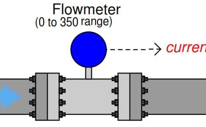


The flowmeter is too close to the valve.