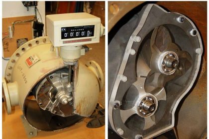
Turbine flow meters are designed with wear-resistant internal components to provide trouble-free operation and long service life.
Turbine Flow Meter
Fluid entering the flow meter is first conditioned by the inlet flow straightener which reduces turbulence in the fluid.
The moving fluid causes the rotor to spin at a speed that is proportional to its flow rate.
As the blades on the rotor pass through the magnetic field of the pickup, an electronic pulse is generated.
This pulse train signal can then be used to monitor the fluids actual flow rate or the total amount of fluid that has passed through the flow meter.
The number of electronic pulses generated by the meter, per unit volume, is known as its K-Factor. Each flow meter is calibrated to find its unique K-Factor, which is supplied with the flow meter when purchased.
Installation Procedure
Before installation, the flow meter should be checked for foreign material and to ensure that the rotor spins freely.
All upstream fluid lines should also be cleared of any debris. Also, make sure that fluid flow has been shut off and all pressure in the lines has been released prior to installing the flow meter into an existing system.
The flow meter must be installed with the flow direction arrow pointing in the direction of fluid flow. The flow direction arrow can be found on the side of the flow meter.
The flow meter is designed to work in any orientation, but the preferred orientation is to have the meter installed in horizontal piping.
The fluid to be measured is recommended to be filtered. The best location for the filter or strainer would be upstream of the flow meter, after any other system components, while maintaining straight piping requirements.

The preferred plumbing setup is one containing a bypass line (above figure). This allows meter inspection and repair without interrupting flow, as well as the ability to cycle the fluid through the system filter before diverting to the flow meter.
If a bypass line is not used, it is important that all flow control valves be located downstream of the flow meter (below figure).

For optimum flow meter performance a minimum length of upstream and downstream piping is required.
It is recommended that a minimum length equal to 10 pipe diameters of straight pipe be installed directly on the upstream side of the flow meter and 5 pipe diameters on the downstream side of the flow meter.
This helps to eliminate turbulence in the fluid. Having shorter pipe lengths, other system components and elbows to close to the flow meter may adversely affect the accuracy and repeatability of the flow meter. Piping should be the same size as the meter bore or port size.
Do not locate the flow meter or the connection cable close to electric motors, transformers, sparking devices, high voltage lines or place connecting cable in a conduit with wire supplying power for such devices.
These devices can induce false signals in the flow meter coil or cable, causing the meter to read inaccurately.
Start-Up Procedure
The following procedures should be observed when installing the flow meter and running it for the first time after installation.
- After meter installation, close the isolation valves and open the bypass valve. Flow liquid through the system for a sufficient time to eliminate any air or gas in the flow line.
- Slowly open the upstream isolating valve to fill the flow meter with liquid.
- Open the downstream isolating valve to start fluid flow through the flow meter, permitting the flow meter to start to operate, then close the bypass valve completely.
- If the downstream valve is used as a flow control valve, adjust the valve to provide the required flow rate through the flow meter.
Note :
- Air and gas, running at a high velocity, can damage the internal components of the flow meter.
- Never hit a flow meter, empty of fluid, with full fluid flow. This fluid shock or hammering effect on the internals of the flow meter can permanently damage the internal components.
Operation Limitations
We will discuss some important operation limitations regarding the turbine flow meter here.
- Corrosion,
- Pulsation,
- Vibration,
- Filter/Strainer
Corrosion
The internal parts are constructed from stainless steels and tungsten carbide with a nickel binder. Ensure that your fluid is compatible with these materials.
Incompatible fluids could deteriorate the internal parts, causing inaccurate readings. Consult the manufacturer of the fluid regarding its chemical compatibility with these materials.
Pulsation
Severe fluid pulsation will have a negative effect on the flow meters accuracy and may shorten the life of the flow meter.
Vibration
Severe vibration may decrease the life of the flow meter.
Filter/Strainer
A filter or strainer is recommended to be installed upstream of the flow meter. Particles entering the flow meter may cause pitting of the internal components, reducing its service life.
Build up of particles on rotating parts can adversely affect the performance of the flow meter.
Turbine Flowmeter Troubleshooting Guide


Reference: Aw-lake Turbine Flow Meter Manual
If you liked this article, then please subscribe to our YouTube Channel for Instrumentation, Electrical, PLC, and SCADA video tutorials.
You can also follow us on Facebook and Twitter to receive daily updates.
Read Next:
- Continuous Flow Measurement
- Liquid Flow Control Loop Controller
- What is a Paddle wheel flow meter?
- Fundamentals of Valves and Types
- DP Flow Transmitter Re-Ranging


Instrumentation tool is very helpful site for engineers
Thanks
thanks for this article!