Troubleshooting is the application of logical thinking combined with a thorough knowledge of circuit or system operation to identify and correct a malfunction. A systematic approach to troubleshooting consists of three steps: analysis, planning, and measuring. A defective circuit or system is one with a known good input but with no output or an incorrect output.
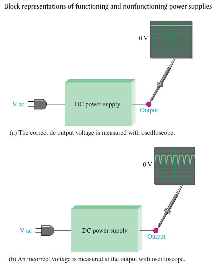
For example, in Figure (a), a properly functioning dc power supply is represented by a single block with a known input voltage and a correct output voltage. A defective dc power supply is represented in part (b) as a block with an input voltage and an incorrect output voltage.
Analysis
The first step in troubleshooting a defective circuit or system is to analyze the problem, which includes identifying the symptom and eliminating as many causes as possible.In the case of the power supply example illustrated in Figure (b), the symptom is that the output voltage is not a constant regulated dc voltage.
This symptom does not tell you much about what the specific cause may be. In other situations, however, a particular symptom may point to a given area where a fault is most likely.
The first thing you should do in analyzing the problem is to try to eliminate any obvious causes. In general, you should start by making sure the power cord is plugged into an active outlet and that the fuse is not blown. In the case of a battery-powered system, make sure the battery is good. Something as simple as this is sometimes the cause of a problem.
However, in this case, there must be power because there is an output voltage. Beyond the power check, use your senses to detect obvious defects, such as a burned resistor,broken wire, loose connection, or an open fuse. Since some failures are temperature dependent, you can sometimes find an overheated component by touch.
However, be very cautious in a live circuit to avoid possible burn or shock. For intermittent failures, the circuit may work properly for awhile and then fail due to heat buildup. As a rule, you should always do a sensory check as part of the analysis phase before proceeding.
Planning
In this phase, you must consider how you will attack the problem. There are three possible approaches to troubleshooting most circuits or systems.
- Start at the input (the transformer secondary in the case of a dc power supply) where there is a known input voltage and work toward the output until you get an incorrect measurement. When you find no voltage or an incorrect voltage, you have narrowed the problem to the part of the circuit between the last test point where the voltage was good and the present test point. In all troubleshooting approaches, you must know what the voltage is supposed to be at each point in order to recognize an incorrect measurement when you see it.
- Start at the output of a circuit and work toward the input. Check for voltage at each test point until you get a correct measurement. At this point, you have isolated the problem to the part of the circuit between the last test point and the current test point where the voltage is correct.
- Use the half-splitting method and start in the middle of the circuit. If this measurement shows a correct voltage, you know that the circuit is working properly from the input to that test point. This means that the fault is between the current test point and the output point, so begin tracing the voltage from that point toward the output. If the measurement in the middle of the circuit shows no voltage or an incorrect voltage, you know that the fault is between the input and that test point.
Therefore, begin tracing the voltage from the test point toward the input. For illustration, let’s say that you decide to apply the half-splitting method using an oscilloscope.
Measurement
The half-splitting method is illustrated in Below Figure with the measurements indicating a particular fault (open filter capacitor in this case). At test point 2 (TP2) you observe a full-wave rectified voltage that indicates that the transformer and rectifier are working properly.
This measurement also indicates that the filter capacitor is open, which is verified by the full-wave voltage at TP3. If the filter were working properly, you would measure a dc voltage at both TP2 and TP3. If the filter capacitor were shorted, you would observe no voltage at all of the test points because the fuse would most likely be blown.
A short anywhere in the system is very difficult to isolate because, if the system is properly fused, the fuse will blow immediately when a short to ground develops.
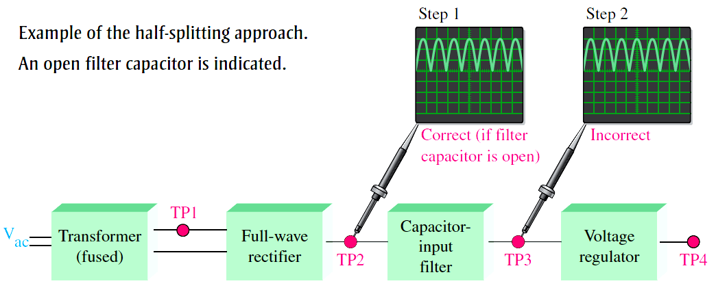
Fig : Example of the half-splitting approach. An open filter capacitor is indicated.
For the case illustrated in Figure, the half-splitting method took two measurements to isolate the fault to the open filter capacitor. If you had started from the transformer output, it would have taken three measurements; and if you had started at the final output, it would have also taken three measurements, as illustrated in Figure.
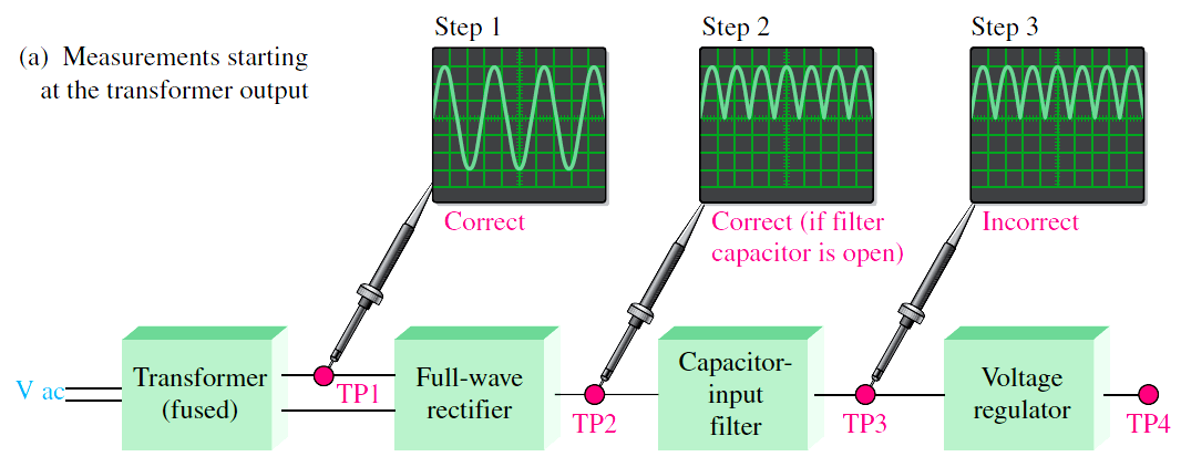
Fig (a) : Measurements starting at the transformer output
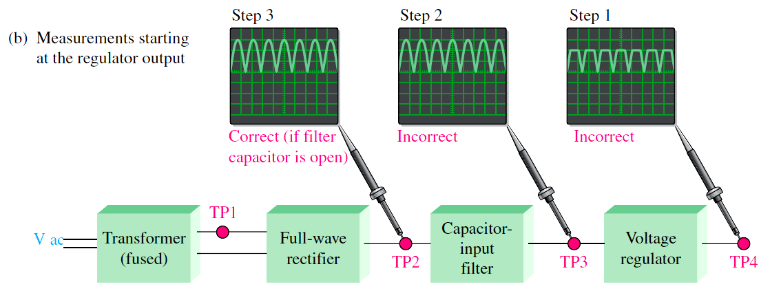
Fig (b) : Measurements starting at the regulator output
Fig : In this particular case, the two other approaches require more oscilloscope measurements than the half-splitting approach in Figure.