Inst ToolsInst ToolsInst Tools
  • Courses
  • Automation
    • PLC
    • Control System
    • Safety System
    • Communication
    • Fire & Gas System
  • Instrumentation
    • Design
    • Pressure
    • Temperature
    • Flow
    • Level
    • Vibration
    • Analyzer
    • Control Valve
    • Switch
    • Calibration
    • Erection & Commissioning
  • Interview
    • Instrumentation
    • Electrical
    • Electronics
    • Practical
  • Q&A
    • Instrumentation
    • Control System
    • Electrical
    • Electronics
    • Analog Electronics
    • Digital Electronics
    • Power Electronics
    • Microprocessor
  • Request
Search
  • Books
  • Software
  • Projects
  • Process
  • Tools
  • Basics
  • Formula
  • Power Plant
  • Root Cause Analysis
  • Electrical Basics
  • Animation
  • Standards
  • 4-20 mA Course
  • Siemens PLC Course
Reading: Trip Valve Principle
Share
Font ResizerAa
Inst ToolsInst Tools
Font ResizerAa
  • Courses
  • Design
  • PLC
  • Interview
  • Control System
Search
  • Courses
  • Automation
    • PLC
    • Control System
    • Safety System
    • Communication
    • Fire & Gas System
  • Instrumentation
    • Design
    • Pressure
    • Temperature
    • Flow
    • Level
    • Vibration
    • Analyzer
    • Control Valve
    • Switch
    • Calibration
    • Erection & Commissioning
  • Interview
    • Instrumentation
    • Electrical
    • Electronics
    • Practical
  • Q&A
    • Instrumentation
    • Control System
    • Electrical
    • Electronics
    • Analog Electronics
    • Digital Electronics
    • Power Electronics
    • Microprocessor
  • Request
Follow US
All rights reserved. Reproduction in whole or in part without written permission is prohibited.
Inst Tools > Blog > Control Valves > Trip Valve Principle

Trip Valve Principle

Last updated: August 25, 2019 10:00 am
Editorial Staff
Control Valves
2 Comments
Share
3 Min Read
SHARE

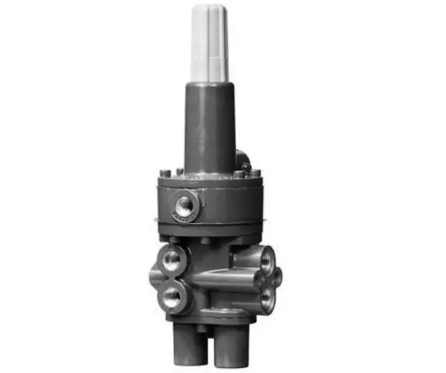
Pressure‐sensing trip valves are for control applications where a specific valve/actuator action is required when supply pressure falls below a specific point. When supply pressure falls below the trip point (see below figure), the trip valve causes the actuator to fail up, lock in the last position, or fail down.

When the supply pressure rises above the trip point, the trip valve automatically resets, allowing the system to return to normal operation. The trip valve can be top‐mounted on a manifold, yoke‐mounted, or bracket‐mounted to match the application requirements.

pressure‐sensing trip valve

Image Courtesy : Emerson
Principle :

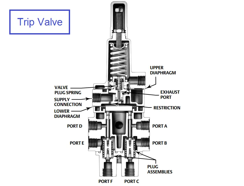
In normal operation, supply pressure loads the upper diaphragm (see below figure) of the unit. The valve plug spring keeps the exhaust port closed.

Supply pressure also loads the lower diaphragm through the restriction, causing the plug assemblies to move down and isolate ports C and F while connecting port A to B and port D to E.

Trip Valve Principle

Image Courtesy : Emerson
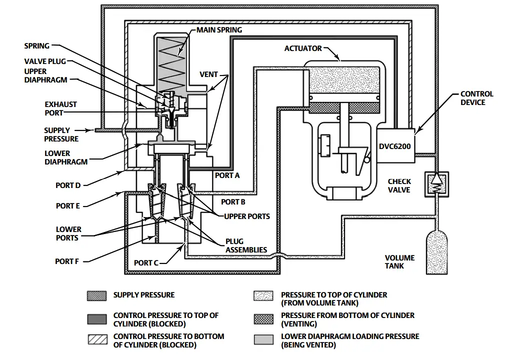
Normal actuator control pressure flows from the control device to the top of the cylinder through ports A and B and to the bottom of the cylinder through ports D and E. A volume tank is charged to maximum supply pressure through a check valve in order to retain maximum supply pressure in the volume tank if supply pressure drops.

When supply pressure falls below the trip point pressure in the fail‐down mode (see below figure), the exhaust port opens, venting the supply pressure that is loading the lower diaphragm. This causes the upper ports of the plug assemblies to close and shut off normal pressure flow from the control device to the actuator.

Volume tank pressure then flows through ports C and B to the top of the actuator cylinder, while pressure in the bottom of the actuator cylinder is vented through ports E and F. The pressure imbalance created forces the actuator piston down.

When supply pressure is restored, it loads the upper and lower diaphragms, causing the trip valve to reset. The exhaust port closes. The upper ports of the plug assemblies open, and the lower ports close.

Normal actuator control pressure flow from the control device is restored through ports A and B and ports D and E. The check valve opens and recharges the volume tank to the maximum supply pressure.

Trip Valve Shown Tripped :

Trip Valve Shown Tripped

Image Courtesy : Emerson
Don't Miss Our Updates
Be the first to get exclusive content straight to your email.
We promise not to spam you. You can unsubscribe at any time.
Invalid email address
You've successfully subscribed !

Continue Reading

Valve Materials Comparison Notes
Rotary Stem Valves
Difference Between Linear Actuator and Rotary Actuator
Quick Exhaust and Air Operated Valves in Instrumentation Circuit
Solenoid Valve Troubleshooting Tips
Advantages and Disadvantages of Valve Actuators
Share This Article
Facebook Whatsapp Whatsapp LinkedIn Copy Link
Share
2 Comments
  • Álvaro A. says:
    December 14, 2020 at 1:45 pm

    I’d like an animation GIF showing flow and switching action. For better understanding of this important device

    Reply
  • barka says:
    August 30, 2023 at 3:26 pm

    than’k for the documents

    Reply

Leave a Reply Cancel reply

Your email address will not be published. Required fields are marked *

Stay Connected

128.3kFollowersLike
69.1kFollowersFollow
210kSubscribersSubscribe
38kFollowersFollow

Categories

Explore More

What is Swing Check Valve ?
Identify Valve Parts Quiz with Answers
Safety Relief Valve Questions & Answers
Control Valve in Nutshell – Valve Design and Selection Factors
Solenoid Valve Working Animation
Types of Valve Actuators
Choke Valve Hydro Testing Procedure
What is Plug Valve ?

Keep Learning

Pneumatic Actuators

Self-Actuated Valves, Pneumatic & Hydraulic Actuators

Control Valve Calibration

How-to do Control Valve Calibration?

Butterfly check valves

What is Butterfly Check Valve ?

Control Valve flow coefficient (Cv)

Why we Measure Control Valve flow coefficient (Cv)?

Solenoid Valve Problems and Solutions

Solenoid Valve Problems and Solutions

2-way solenoid valve Normally Closed

What is a 2-way Solenoid Valve ?

How to Do Maintenance of Control Valve Which is Stuck in Field?

How to Do Maintenance of Control Valve Which is Stuck in Field?

Difference between Butterfly Valves and Ball Valves

Difference between Butterfly Valves and Ball Valves

Learn More

Digital Control Valve (DCV) Calibration Procedure

Digital Control Valve (DCV) Calibration Procedure

ESP8266 WiFi Module Projects

ESP8266 WiFi Module Projects for Engineering Students

Servo Tank Gauge Level Principle

Servo Tank Gauges Working Principle

Fuse in a Electrical Circuit

Advantages & Disadvantages of Fuse in a Electrical Circuit

Bucket Steam Trap

Bucket Steam Trap

On Delay Timer using PLC

ON Delay Timer using PLC

Latest Control Valves Interview Questions

Control Valve Interview Questions and Answers

PLC analog output card

PLC Analog I/O and Network I/O

Menu

  • About
  • Privacy Policy
  • Copyright

Quick Links

  • Learn PLC
  • Helping Hand
  • Part Time Job

YouTube Subscribe

Follow US
All rights reserved. Reproduction in whole or in part without written permission is prohibited.
Welcome Back!

Sign in to your account

Username or Email Address
Password

Lost your password?