Inst ToolsInst ToolsInst Tools
  • Courses
  • Automation
    • PLC
    • Control System
    • Safety System
    • Communication
    • Fire & Gas System
  • Instrumentation
    • Design
    • Pressure
    • Temperature
    • Flow
    • Level
    • Vibration
    • Analyzer
    • Control Valve
    • Switch
    • Calibration
    • Erection & Commissioning
  • Interview
    • Instrumentation
    • Electrical
    • Electronics
    • Practical
  • Q&A
    • Instrumentation
    • Control System
    • Electrical
    • Electronics
    • Analog Electronics
    • Digital Electronics
    • Power Electronics
    • Microprocessor
  • Request
Search
  • Books
  • Software
  • Projects
  • Process
  • Tools
  • Basics
  • Formula
  • Power Plant
  • Root Cause Analysis
  • Electrical Basics
  • Animation
  • Standards
  • 4-20 mA Course
  • Siemens PLC Course
Reading: Transistor as Amplifier
Share
Notification Show More
Font ResizerAa
Inst ToolsInst Tools
Font ResizerAa
  • Courses
  • Design
  • PLC
  • Interview
  • Control System
Search
  • Courses
  • Automation
    • PLC
    • Control System
    • Safety System
    • Communication
    • Fire & Gas System
  • Instrumentation
    • Design
    • Pressure
    • Temperature
    • Flow
    • Level
    • Vibration
    • Analyzer
    • Control Valve
    • Switch
    • Calibration
    • Erection & Commissioning
  • Interview
    • Instrumentation
    • Electrical
    • Electronics
    • Practical
  • Q&A
    • Instrumentation
    • Control System
    • Electrical
    • Electronics
    • Analog Electronics
    • Digital Electronics
    • Power Electronics
    • Microprocessor
  • Request
Follow US
All rights reserved. Reproduction in whole or in part without written permission is prohibited.
Inst Tools > Blog > Electronic Devices & Circuits > Transistor as Amplifier

Transistor as Amplifier

Last updated: September 27, 2016 3:58 pm
Editorial Staff
Electronic Devices & Circuits
No Comments
Share
1 Min Read
SHARE

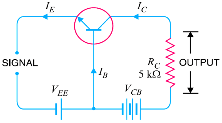
A transistor raises the strength of a weak signal and thus acts as an amplifier. The Below Fig shows the basic circuit of a transistor amplifier. The weak signal is applied between emitter-base junction and output is taken across the load RC connected in the collector circuit.

In order to achieve faithful amplification, the input circuit should always remain forward biased. To do so, a d.c. voltage VEE is applied in the input circuit in addition to the signal as shown. This d.c. voltage is known as bias voltage and its magnitude is such that it always keeps the input circuit forward biased regardless of the polarity of the signal.

Transistor as Amplifier

As the input circuit has low resistance, therefore, a small change in signal voltage causes an appreciable change in emitter current. This causes almost the same change in collector current due to transistor action. The collector current flowing through a high load resistance RC produces a large voltage across it. Thus, a weak signal applied in the input circuit appears in the amplified form in the collector circuit. It is in this way that a transistor acts as an amplifier.

Don't Miss Our Updates
Be the first to get exclusive content straight to your email.
We promise not to spam you. You can unsubscribe at any time.
Invalid email address
You've successfully subscribed !

Continue Reading

Basics of Ohm’s Law
Ideal Diode Characteristics
Seven Segment Display Working Principle
Forward Bias & Reverse Bias of a Diode
What is a Memristor? Principle, Advantages, Applications
Transistor as a Switch Working Principle
Share This Article
Facebook Whatsapp Whatsapp LinkedIn Copy Link
Share
Leave a Comment

Leave a Reply Cancel reply

Your email address will not be published. Required fields are marked *

Stay Connected

128.3kFollowersLike
69.1kFollowersFollow
210kSubscribersSubscribe
38kFollowersFollow

Categories

Explore More

Combining Independent Current Sources in Parallel
Series and Parallel Resistors
Light Emitting Diode Operation
VI Characteristic of a Diode
Transistor Stabilisation
Testing a Transistor with a Digital Multimeter
Transistor Voltage Divider Bias
Capacitor Filter Operation

Keep Learning

zener-diode-as-voltage-regulator

Operation of Zener Diode Voltage Regulator

pn-junction-with-depletion-layer

How a PN Junction Formed in a Diode

phototransistor-circuit

Phototransistor Circuit Example

Transistor Collector Feedback Bias

Transistor Collector Feedback Bias

diode-clamper-circuit

Full Wave Voltage Doubler using Diodes

pi filter Operation

pi filter Operation

Classification of Bridge Circuits

Classification of Bridge Circuits

Power MOSFET Safe Operating Area

Power MOSFET Safe Operating Area

Learn More

Power Electronics Objective Questions

Three Phase Converter Test Questions

Best Online Courses to Learn Electrical Engineering

Best Online Courses to Learn Electrical Engineering

Motor Slip Calculation

Electrical Motor Terms and Concepts

Electrical Machines Questions and Answers

DC Generators Characteristics Quiz

Run 4 Motors Sequentially from Same Push button PLC Program

Run 4 Motors Sequentially from Same Push button PLC Program

Phase Failure Relay

Why is Phase Failure Relay Required in LV Panels?

Insulators, Conductors and Semiconductors

Failure Demand in Safety Control Circuit

Safety Instrumented System Module Failure

Menu

  • About
  • Privacy Policy
  • Copyright

Quick Links

  • Learn PLC
  • Helping Hand
  • Part Time Job

YouTube Subscribe

Follow US
All rights reserved. Reproduction in whole or in part without written permission is prohibited.
Welcome Back!

Sign in to your account

Username or Email Address
Password

Lost your password?