Inst ToolsInst ToolsInst Tools
  • Courses
  • Automation
    • PLC
    • Control System
    • Safety System
    • Communication
    • Fire & Gas System
  • Instrumentation
    • Design
    • Pressure
    • Temperature
    • Flow
    • Level
    • Vibration
    • Analyzer
    • Control Valve
    • Switch
    • Calibration
    • Erection & Commissioning
  • Interview
    • Instrumentation
    • Electrical
    • Electronics
    • Practical
  • Q&A
    • Instrumentation
    • Control System
    • Electrical
    • Electronics
    • Analog Electronics
    • Digital Electronics
    • Power Electronics
    • Microprocessor
  • Request
Search
  • Books
  • Software
  • Projects
  • Process
  • Tools
  • Basics
  • Formula
  • Power Plant
  • Root Cause Analysis
  • Electrical Basics
  • Animation
  • Standards
  • 4-20 mA Course
  • Siemens PLC Course
Reading: Transformer Impedance Ratio
Share
Font ResizerAa
Inst ToolsInst Tools
Font ResizerAa
  • Courses
  • Design
  • PLC
  • Interview
  • Control System
Search
  • Courses
  • Automation
    • PLC
    • Control System
    • Safety System
    • Communication
    • Fire & Gas System
  • Instrumentation
    • Design
    • Pressure
    • Temperature
    • Flow
    • Level
    • Vibration
    • Analyzer
    • Control Valve
    • Switch
    • Calibration
    • Erection & Commissioning
  • Interview
    • Instrumentation
    • Electrical
    • Electronics
    • Practical
  • Q&A
    • Instrumentation
    • Control System
    • Electrical
    • Electronics
    • Analog Electronics
    • Digital Electronics
    • Power Electronics
    • Microprocessor
  • Request
Follow US
All rights reserved. Reproduction in whole or in part without written permission is prohibited.
Inst Tools > Blog > Electrical Theory > Transformer Impedance Ratio

Transformer Impedance Ratio

Last updated: August 6, 2018 10:19 pm
Editorial Staff
Electrical Theory
No Comments
Share
1 Min Read
SHARE

Maximum power is transferred from one circuit to another through a transformer when the impedances are equal, or matched.

A transformer winding constructed with a definite turns ratio can perform an impedance matching function.

The turns ratio will establish the proper relationship between the primary and secondary winding impedances.

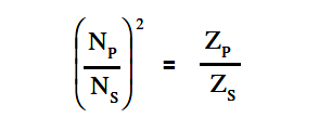
The ratio between the two impedances is referred to as the impedance ratio and is expressed by using below Equation.

Transformer Impedance Ratio - 1

Another way to express the impedance ratio is to take the square root of both sides of above Equation. This puts the ratio in terms of the turns ratio, which is always given for a transformer.
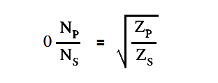
Transformer Impedance Ratio - 2

where

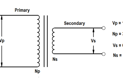
NP = number of turns in the primary
NS = number of turns in the secondary
ZP= impedance of primary
ZNS= impedance of secondary

Don't Miss Our Updates
Be the first to get exclusive content straight to your email.
We promise not to spam you. You can unsubscribe at any time.
Invalid email address
You've successfully subscribed !

Continue Reading

DC Generator Theory
Voltage Divider
What is Electricity ?
DC Generator
Calculate Power in Parallel RL Circuit
Electrical System Components and Protection Devices
Share This Article
Facebook Whatsapp Whatsapp LinkedIn Copy Link
Share
Leave a Comment

Leave a Reply Cancel reply

Your email address will not be published. Required fields are marked *

Stay Connected

128.3kFollowersLike
69.1kFollowersFollow
210kSubscribersSubscribe
38kFollowersFollow

Categories

Explore More

D’Arsonval Meter Movement
AC Generator Theory
Series Open Circuit Faults
Half-Wave Rectifier Circuit
Capacitor
Generator Action in a Motor
Ground Detector Principle
Series and Parallel Inductors

Keep Learning

Inductive Time Constant

Inductive Time Constant

Shunt-Wound DC Motor

Shunt-Wound Motor Operation

Types of Capacitors

Types of Capacitors

Calculate Power in Series RL Circuit

Calculate Power in Series RL Circuit

Three Phase Wattmeter principle

Ampere Hour Meter

Core-Type Transformer

Transformer Theory of Operation

Electric Short Circuit

Electric Circuit : Open & Short Circuits

Potential Difference Across a Conductor Causes a Current to Flow

Conductor, Insulator, Resistor and Current Flow

Learn More

Paddle switch Working Principle

Paddle Switch Working Principle

Instrumentation Calculator

Instrumentation Calculator Android App

Siemens micro memory card

Micro Memory Card (MMC) in Siemens PLC

non-contact and guided-wave radar level transmitters

Radar Level Measurement

Erratic Stroking Control Valves

Erratic Stroking Control Valves Delaying the Shutdown Plant Restart

Field Instruments enclosures

Pressure Transmitter Heated Enclosures

What is an Automated Guided Vehicle

What is an Automated Guided Vehicle?

Fence grounding specifications

All About Electric Fence Gates

Menu

  • About
  • Privacy Policy
  • Copyright

Quick Links

  • Learn PLC
  • Helping Hand
  • Part Time Job

YouTube Subscribe

Follow US
All rights reserved. Reproduction in whole or in part without written permission is prohibited.
Welcome Back!

Sign in to your account

Username or Email Address
Password

Lost your password?