Design the traffic lights ladder diagram using timers in the PLC programming to control the Red, Yellow, and Green signals.
Note: The content provided in this PLC programming example is for study purposes and is meant to help individuals with ladder logic basics.
Traffic Lights
Problem Statement:
Design a PLC ladder logic for the following application.
This is a basic traffic lights PLC program. We are using one toggle switch to control 3 Lights. Turn ON the following signals in sequence.
- Green Light for 20 seconds,
- Yellow Light for 5 seconds and
- Red Light for 15 seconds.
PLC Tutorial Videos
Learn PLC programming in simple steps. Select the required PLC course on “Instrumentation Tools” YouTube channel and complete the training series.
This video explains the traffic lights PLC logic.
Inputs and Outputs
Digital Inputs:
Start Button: I0.0
Digital Outputs:
Green: Q0.0
Yellow: Q0.1
Red: Q0.2
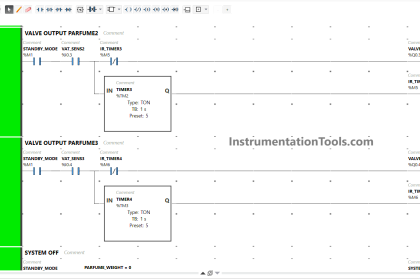
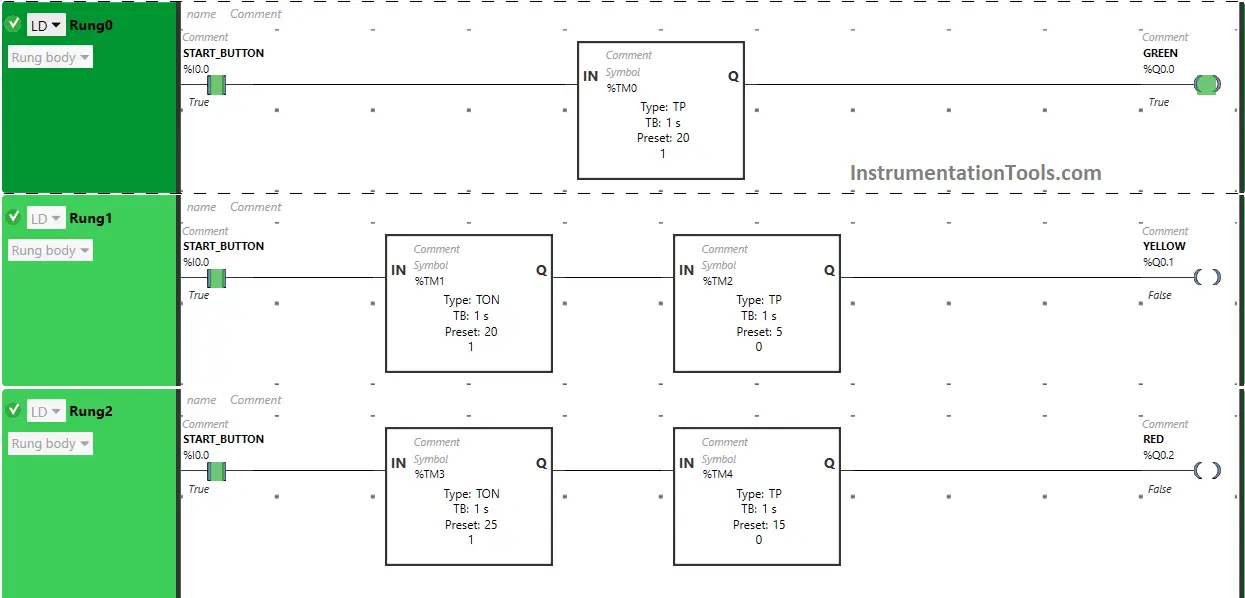
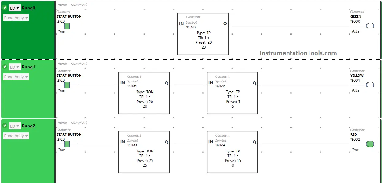
Ladder Diagram using Timers

Program Description
We have used Normally Open Contact for the Start Button(I0.0).
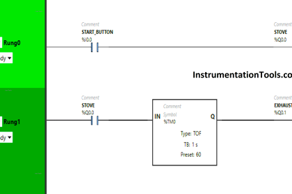
In Rung 0:
- Normally Open Contact is used for the Start Button (I0.0) to Turn ON the output Green (Q0.0).
- Timer TP is used to Turn ON the output Green (Q0.0) for a limited time.
In Rung 1:
- Normally Open Contact is used for the Start Button (I0.0) to Turn ON the output Yellow (Q0.1).
- Timer TON is used to delay the turning ON time of the output Yellow (Q0.1) for some time.
- Timer TP is used to Turn ON the output Yellow (Q0.1) for a limited time.
In Rung 2:
- Normally Open Contact is used for the Start Button (I0.0) to Turn ON the output Red (Q0.2).
- Timer TON is used to delay the turning ON time of the output Red (Q0.2) for some time.
- Timer TP is used to Turn ON the output Red (Q0.2) for a limited time.
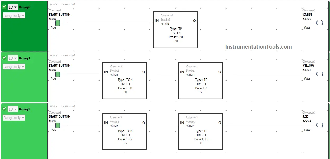
Program Testing
Let’s do the PLC program testing and observe the outputs status.
Rung 0:
When Start Button (I0.0) is turned ON, the signal will flow through Start Button (I0.0) as Normally Open Contact is used for Start Button (I0.0).
The output Green (Q0.0) turns ON for 20 seconds because Timer Function Block type TP is used to turn ON the output Green (Q0.0) for limited time and time is set to 20 seconds. After 20 seconds, the output Green (Q0.0) will turn OFF.
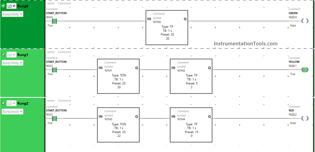
Rung 1:
When Start Button(I0.0) is turned ON, the output Yellow (Q0.1) will turn ON after 20 s ( i.e immediately when the output Green (Q0.0) gets turned OFF) because Timer Function Block type TON is used to delay the turning ON time of the output Yellow (Q0.1) and the time is set to 20 seconds.
The output Yellow (Q0.1) will remain ON only for 5 seconds as we have used Timer Function Block type TP to turn ON the output Yellow (Q0.1) only for limited time and the time is set to 5 seconds. So after 5 seconds, the output Yellow (Q0.1) will turn OFF.
Rung 2:
When Start Button(I0.0) is turned ON, the output Red (Q0.2) will turn ON after 25 seconds ( i.e immediately when the output Yellow (Q0.1) gets turned OFF) because Timer Function Block type TON is used to delay the turning ON time of the output Red (Q0.2) and the time is set to 25 seconds.
After 25 seconds, the output Red (Q0.2) will turn ON. The output Red (Q0.2) will remain ON only for 15 seconds as we have used Timer Function Block type TP to turn ON the output Red (Q0.2) only for limited time and the time is set to 15 seconds. So after 15 seconds, the output Red (Q0.2) will turn OFF.
If you liked this article, please subscribe to our YouTube Channel for PLC and SCADA video tutorials.
You can also follow us on Facebook and Twitter to receive daily updates.
Read Next:
- 4 Way Traffic Light Control System
- Siemens S7 CPU LED Status & Errors
- PLC-to-PLC Communication Project
- Data Sharing Between PLC Systems
- One-Shot Rising and Falling Edge