Inst ToolsInst ToolsInst Tools
  • Ask
  • Courses
  • Videos
  • Q & A
    • Interview
      • Instrumentation
      • Electronics
      • Electrical
      • Practical Questions
    • MCQ
      • Instrumentation MCQ
      • Electrical MCQ
      • Electronics MCQ
      • Control Systems MCQ
      • Analog Electronics MCQ
      • Digital Electronics MCQ
      • Power Electronics MCQ
      • Microprocessor MCQ
      • Multiple Choice Questions
  • EE
    • Electronics
      • Electronics Q & A
      • Electronic Basics
      • Electronic Devices & Circuits
      • Electronics Animation
      • Digital Electronics
    • Electrical
      • Electrical Basics
      • Electrical Q & A
      • Power Electronics
      • Electrical Machines
      • Electrical Animation
      • Power Systems
      • Switchgear & Protection
      • Transmission & Distribution
  • Measure
    • Control Valves
    • Calibration
    • Temperature
    • Pressure
    • Flow
    • Level
    • Analyzers
    • Switches
    • Vibration
    • Solenoid Valve
  • Control
    • PLC Tutorials
    • Control Systems
    • Safety Instrumented System (SIS)
    • Communication
    • Fire & Gas System
  • More
    • Design
    • Tools
    • Animation
    • Basics
    • Formulas
    • Standards
    • TextBooks
    • Common
    • Software
    • Excel Tools
    • Erection & Commissioning
    • Process Fundamentals
    • Videos
    • Books
Search
All rights reserved. Reproduction in whole or in part without written permission is prohibited.
Reading: Time Base Generator
Share
Notification Show More
Font ResizerAa
Inst ToolsInst Tools
Font ResizerAa
  • Courses
  • PLC Tutorials
  • Control Systems
Search
  • Ask
  • Courses
  • Videos
  • Q & A
    • Interview
    • MCQ
  • EE
    • Electronics
    • Electrical
  • Measure
    • Control Valves
    • Calibration
    • Temperature
    • Pressure
    • Flow
    • Level
    • Analyzers
    • Switches
    • Vibration
    • Solenoid Valve
  • Control
    • PLC Tutorials
    • Control Systems
    • Safety Instrumented System (SIS)
    • Communication
    • Fire & Gas System
  • More
    • Design
    • Tools
    • Animation
    • Basics
    • Formulas
    • Standards
    • TextBooks
    • Common
    • Software
    • Excel Tools
    • Erection & Commissioning
    • Process Fundamentals
    • Videos
    • Books
Follow US
All rights reserved. Reproduction in whole or in part without written permission is prohibited.
Inst Tools > Blog > Electronic Devices & Circuits > Time Base Generator

Time Base Generator

Last updated: April 1, 2018 8:07 am
Editorial Staff
Electronic Devices & Circuits
No Comments
Share
5 Min Read
SHARE

It has been mentioned earlier that the time domain oscilloscopes require a sweep generator that is linear with time for the x-axis display. The motion of spot on the screen from extreme left to extreme right is called sweep.

Contents
Why sweep generator is called time base generator?Requirements of time base:Principle of time base generatorHold off time:Waiting time:

The generator which generates a waveform which is responsible for the movement of spot on screen horizontally is called time base generator or sweep generator. The sweep circuit along with the display gating functions is called time bases.

The linear sweep moves the spot from left to right while the movement of spot from right to left is not visible. This portion of waveform generated by time base is called flyback or retrace. During this time, the cathode ray tube is blanked.

The time base generator also controls the rate at which the spot moves, across the screen. This rate is to be adjusted from front panel control.

Why sweep generator is called time base generator?

All the time dependent waveforms need x-axis to be calibrated as time axis. The sweep generator produces the movement of spot on screen such that it acts as a time axis or time base for the waveforms to be displayed. Hence the sweep generator is also called time base generator.

The two front panel controls which are used to control rate and duration of time base waveform are time/division and time variable control.

Note: the trigger circuit ensures that the horizontal sweep starts at the same point of the vertical input signal.

Requirements of time base:

The time base requirements are:

  1. Sweep time variations from 10nsec to 5 sec per division.
  2. Time accuracy is better than 3%.
  3. Linearity better is better than 1% across the cathode ray tube.
  4. Ten times expansion in the horizontal amplifier which allows 1 nsec per division displays for very high speed transients.
  5. The speed of the spot should be constant across the entire screen.
  6. The spot should be invisible while tracing from right to left and should be visible only from left to right.

Principle of time base generator

The basic sweep generator uses the charging characteristics of a capacitor to generate linear risetime voltages. Linearly increasing ramp which becomes zero with very short duration of time ensures that the spot is visible from left to right and invisible from right to left.

The image below shows a capacitor charged from a constant current source.

principle of time base generator

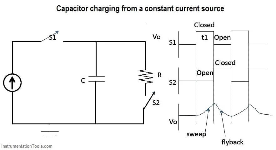
When switch S1 is closed, S2 is open and capacitor charges to produce linear ramp at the output. The sweep rate can be controlled by changing the value of capacitor or charging current.

Reaching to the maximum value of ramp voltage, the switch S2 is closed and S1 is open. Thus capacitor gets discharged through the resistance R. this is called flyback or retrace. The time t1 is called sweep time. The circuit is a sort of relaxation oscillator which generates saw tooth waveform. But this circuit has less accuracy. The bootstrap techniques allow much greater linearity but he techniques are much more costly.

During the sweep time, the spot moves from left to right. During retrace, the screen is blanked and spot comes back to its starting level but its movement from right to left is invisible.
Practically a trigger circuit is associated with the time base generator. This circuit generates a trigger pulse which activates the time base generator to produce a ramp.

Now when one cycle, sweep and retrace is completed then time base generator takes certain time to start the next cycle. This time is divided into two types as hold off time and waiting time.

Hold off time:

Through the trigger circuit applies the pluse immediately after completion of cycle, the time base generator takes some time to start the ramp. This time is required to stabilize the flyback circuitry. This time is called hold off time.

Waiting time:

Now when trigger pulse is generated b trigger circuit, the pulse has to cross certain reference level so as to activate the time base generator. This reference level is called trigger threshold.

Now after the end of hold off period, though circuit is ready, due to trigger threshold crossing, the pulse takes some time to activate time base generator. So time required by the triggering pulses to cross the trigger threshold is called waiting time.

Don't Miss Our Updates
Be the first to get exclusive content straight to your email.
We promise not to spam you. You can unsubscribe at any time.
Invalid email address
You've successfully subscribed !

Recommended Articles

Full Wave Rectifier
pi filter Operation
Diodes Voltage Tripler
Center Tapped Full Wave Rectifier Operation
Electron Gun of Cathode Ray Tube
Schottky Diode Working Principle
Share This Article
Facebook Whatsapp Whatsapp LinkedIn Copy Link
Share
Leave a Comment

Leave a Reply Cancel reply

Your email address will not be published. Required fields are marked *

Stay Connected

128.3kFollowersLike
69.1kFollowersFollow
208kSubscribersSubscribe
38kFollowersFollow

Categories

Recent Comments

  • William Snyder on Top Non-PLC Certification Courses for Automation Professionals
  • Kamli on Top Free PLC Software
  • Guifty Shimica on Top Non-PLC Certification Courses for Automation Professionals
  • Guifty Shimica on Top Non-PLC Certification Courses for Automation Professionals

Related Articles

Types of Resistors

Types of Resistors

capacitor-filter

Capacitor Filter Working Principle

Reverse Voltage Characteristics of Photo diode

Characteristics of Photo diode

Short Circuit and Open Circuit

Short Circuit and Open Circuit

Choke Input Filter Operation

Choke Input Filter Operation

MOSFET VI Characteristics

Power MOSFET

p-type-semiconductor

N Type and P Type Semiconductors

Basic Transistor Amplifier Circuit Principle

Basic Transistor Amplifier Circuit Principle

More Articles

How Nuclear Radiation is used to Measure Coke Dust Level?

How Nuclear Radiation is used to Measure Coke Dust Level?

Weigh feeders Principle

What is a Weigh Feeder?

Pressure Gauge Accessories

Pressure Gauge Accessories

How to Test a Transistor

How to Test a Transistor ?

PLC Sequence Programming Ladder Logic

PLC Sequence Programming Ladder Logic

Free WinCC SCADA Training Course

Free SCADA Training Course

Electromagnetic Fields Objective Questions

Electromagnetic Field Theory Questions and Answers

Interference Immunity (EMC)

Basics of Electromagnetic compatibility (EMC)

Follow US
All rights reserved. Reproduction in whole or in part without written permission is prohibited.
Welcome Back!

Sign in to your account

Username or Email Address
Password

Lost your password?