Inst ToolsInst ToolsInst Tools
  • Courses
  • Automation
    • PLC
    • Control System
    • Safety System
    • Communication
    • Fire & Gas System
  • Instrumentation
    • Design
    • Pressure
    • Temperature
    • Flow
    • Level
    • Vibration
    • Analyzer
    • Control Valve
    • Switch
    • Calibration
    • Erection & Commissioning
  • Interview
    • Instrumentation
    • Electrical
    • Electronics
    • Practical
  • Q&A
    • Instrumentation
    • Control System
    • Electrical
    • Electronics
    • Analog Electronics
    • Digital Electronics
    • Power Electronics
    • Microprocessor
  • Request
Search
  • Books
  • Software
  • Projects
  • Process
  • Tools
  • Basics
  • Formula
  • Power Plant
  • Root Cause Analysis
  • Electrical Basics
  • Animation
  • Standards
  • 4-20 mA Course
  • Siemens PLC Course
Reading: Three Phase Transformer Connections
Share
Font ResizerAa
Inst ToolsInst Tools
Font ResizerAa
  • Courses
  • Design
  • PLC
  • Interview
  • Control System
Search
  • Courses
  • Automation
    • PLC
    • Control System
    • Safety System
    • Communication
    • Fire & Gas System
  • Instrumentation
    • Design
    • Pressure
    • Temperature
    • Flow
    • Level
    • Vibration
    • Analyzer
    • Control Valve
    • Switch
    • Calibration
    • Erection & Commissioning
  • Interview
    • Instrumentation
    • Electrical
    • Electronics
    • Practical
  • Q&A
    • Instrumentation
    • Control System
    • Electrical
    • Electronics
    • Analog Electronics
    • Digital Electronics
    • Power Electronics
    • Microprocessor
  • Request
Follow US
All rights reserved. Reproduction in whole or in part without written permission is prohibited.
Inst Tools > Blog > Electrical Theory > Three Phase Transformer Connections

Three Phase Transformer Connections

Last updated: August 7, 2018 10:37 am
Editorial Staff
Electrical Theory
No Comments
Share
4 Min Read
SHARE

So far, our discussion has dealt with the operation of single-phase transformers. Three-phase transformer operation is identical except that three single-phase windings are used. These windings may be connected in wye, delta, or any combination of the two.

Delta Connection

In the delta connection, all three phases are connected in series to form a closed loop (Figure 1).

delta connected generator

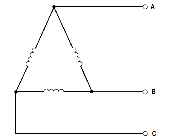
Figure 1 : Delta Connection

Wye Connection

In the wye connection, three common ends of each phase are connected together at a common terminal (marked “N” for neutral), and the other three ends are connected to a three-phase line (Figure 2).

Wye connected generator

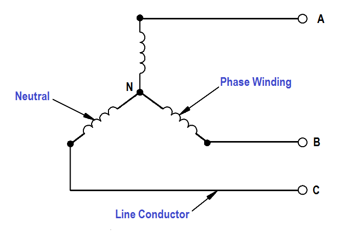
Figure 2 :  Wye Connection

Combinations of Delta and Wye Transformer Connections

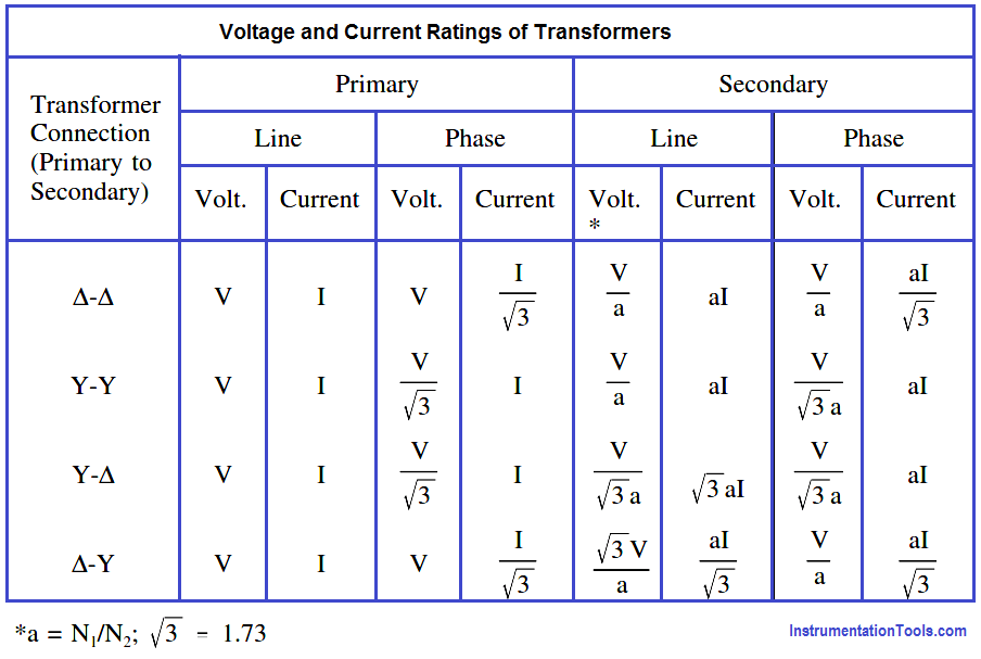
A three-phase transformer may have three separate but identical single-phase (1φ) transformers or a single 3φ unit containing three-phase windings. The transformer windings may be connected to form a 3φ bank in any of four different ways (Figure 3).

Three Phase Transformer Connections

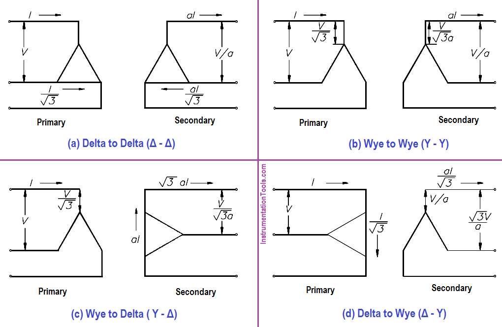
Figure 3 :  3φ Transformer Connections

Figure 3 shows the voltages and currents in terms of applied line voltage (V) and line current (I), where the turns ratio (a) is equal to one. Voltage and current ratings of the individual transformers depend on the connections (Figure 3) and are indicated by below Table for convenience of calculations.

Voltage and Current Ratings of Transformers

Example 1:

If line voltage is 440 V to a 3φ transformer bank, find the voltage across each primary winding for all four types of transformer connections.

Solution :

Δ – Δ : Primary Voltage = V = 440 Volts

Y – Y : Primary Voltage = V/√3 = 440/1.73 = 254.3 volts

Y – Δ : Primary Voltage = V/√3 = 440/1.73 = 254.3 volts

Δ – Y : Primary Voltage = V = 440 Volts

Example 2:

If line current is 10.4 A in a 3φ transformer connection, find the primary phase current.

Solution :

Δ – Δ : Primary Phase Current = I/√3 = 10.4/1.73 = 6 amps

Y – Y : Primary Phase Current = I = 10.4 amps

Y – Δ : Primary Phase Current = I = 10.4 amps

Δ – Y : Primary Phase Current = I/√3 = 10.4/1.73 = 6 amps

Example 3:

Find the secondary line current and phase current for each type of transformer connection, if primary line current is 20 amps, and the turns ratio is 4:1.

Solution :

∆-∆ : Secondary line current = 4(20) = 80 amps

∆-∆ : Secondary Phase current = aI/√3 = (4×20) / 1.73 = 46.2 amps

Y-Y : Second line current = aI = 4(20) = 80 amps

Y-Y : Second phase current = aI = 4(20) = 80 amps

Y-∆ : Second line current = √3aI = 4(20)(1.73) = 138.4 amps

Y-∆ : Second phase current = aI = 4(20) = 80 amps

∆-Y : Second line current = aI/√3 = (4×20) / 1.73 = 46.2 amps

∆-Y : Second phase current = aI/√3 = (4×20) / 1.73 = 46.2 amps

Don't Miss Our Updates
Be the first to get exclusive content straight to your email.
We promise not to spam you. You can unsubscribe at any time.
Invalid email address
You've successfully subscribed !

Continue Reading

Shunt-Wound DC Generators
Transformer Theory of Operation
Transformer Mutual Induction
Series-Wound Motor
Applying Kirchhoff’s Voltage Law
Y and Delta Resistor Network Calculations
Share This Article
Facebook Whatsapp Whatsapp LinkedIn Copy Link
Share
Leave a Comment

Leave a Reply Cancel reply

Your email address will not be published. Required fields are marked *

Stay Connected

128.3kFollowersLike
69.1kFollowersFollow
210kSubscribersSubscribe
38kFollowersFollow

Categories

Explore More

Series Circuit
Impedance in RC Circuits
Synchronous Motors
Voltage and Current Phase Relationships in an Inductive Circuit
Series Open Circuit Faults
Simplified Formulas for Parallel Circuit Resistance Calculations
AC Generator Voltage Regulators
Calculate Power in Series RL Circuit

Keep Learning

Calculate Power in Parallel RL Circuit

Calculate Power in Parallel RL Circuit

Three Phase To Single Phase Wiring Connections

Single Phase Power Wiring Schemes

AC Generator Operation

Types of AC Generators

Electrodynamometer Movement Principle

Electro-Dynamo Meter Movement

Three Phase Wattmeter principle

Ampere Hour Meter

Series Parallel Circuit Analysis

Series – Parallel Circuit Analysis

Types of Batteries

Types of Batteries

Squirrel-Cage Induction Rotor

Induction Motor

Learn More

Hybrid Level Transmitter Principle

Hybrid Level Measurement Principle, Selection, Installation, Limitations and Calibration

Automotive Rail Rapid Transit

Automotive Rail Rapid Transit

Bipolar Junction Transistor Construction

Bipolar Junction Transistor Construction

Instrumentation Cables Questions Answers

Instrumentation Cables Questions & Answers

Inverse Time Circuit Breaker

What are Inverse Time and Instantaneous Trip Circuit Breakers?

PC-Based Motion Controller

Various Types of Delta PLC used in Industrial Automation

Why Grounding

Basics of Grounding

Butterfly valve Principle

Short Notes on Different Valve Types

Menu

  • About
  • Privacy Policy
  • Copyright

Quick Links

  • Learn PLC
  • Helping Hand
  • Part Time Job

YouTube Subscribe

Follow US
All rights reserved. Reproduction in whole or in part without written permission is prohibited.
Welcome Back!

Sign in to your account

Username or Email Address
Password

Lost your password?