Inst ToolsInst ToolsInst Tools
  • Courses
  • Automation
    • PLC
    • Control System
    • Safety System
    • Communication
    • Fire & Gas System
  • Instrumentation
    • Design
    • Pressure
    • Temperature
    • Flow
    • Level
    • Vibration
    • Analyzer
    • Control Valve
    • Switch
    • Calibration
    • Erection & Commissioning
  • Interview
    • Instrumentation
    • Electrical
    • Electronics
    • Practical
  • Q&A
    • Instrumentation
    • Control System
    • Electrical
    • Electronics
    • Analog Electronics
    • Digital Electronics
    • Power Electronics
    • Microprocessor
  • Request
Search
  • Books
  • Software
  • Projects
  • Process
  • Tools
  • Basics
  • Formula
  • Power Plant
  • Root Cause Analysis
  • Electrical Basics
  • Animation
  • Standards
  • 4-20 mA Course
  • Siemens PLC Course
Reading: Three Phase AC Generators
Share
Font ResizerAa
Inst ToolsInst Tools
Font ResizerAa
  • Courses
  • Design
  • PLC
  • Interview
  • Control System
Search
  • Courses
  • Automation
    • PLC
    • Control System
    • Safety System
    • Communication
    • Fire & Gas System
  • Instrumentation
    • Design
    • Pressure
    • Temperature
    • Flow
    • Level
    • Vibration
    • Analyzer
    • Control Valve
    • Switch
    • Calibration
    • Erection & Commissioning
  • Interview
    • Instrumentation
    • Electrical
    • Electronics
    • Practical
  • Q&A
    • Instrumentation
    • Control System
    • Electrical
    • Electronics
    • Analog Electronics
    • Digital Electronics
    • Power Electronics
    • Microprocessor
  • Request
Follow US
All rights reserved. Reproduction in whole or in part without written permission is prohibited.
Inst Tools > Blog > Electrical Theory > Three Phase AC Generators

Three Phase AC Generators

Last updated: August 5, 2018 9:11 pm
Editorial Staff
Electrical Theory
No Comments
Share
3 Min Read
SHARE

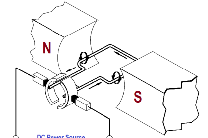
The principles of a three-phase generator are basically the same as that of a single-phase generator, except that there are three equally-spaced windings and three output voltages that are all 120° out of phase with one another. Physically adjacent loops (below Figure) are separated by 60° of rotation; however, the loops are connected to the slip rings in such a manner that there are 120 electrical degrees between phases.

The individual coils of each winding are combined and represented as a single coil. The significance of below Figure is that it shows that the three-phase generator has three separate armature windings that are 120 electrical degrees out of phase.

Three Phase AC Generators

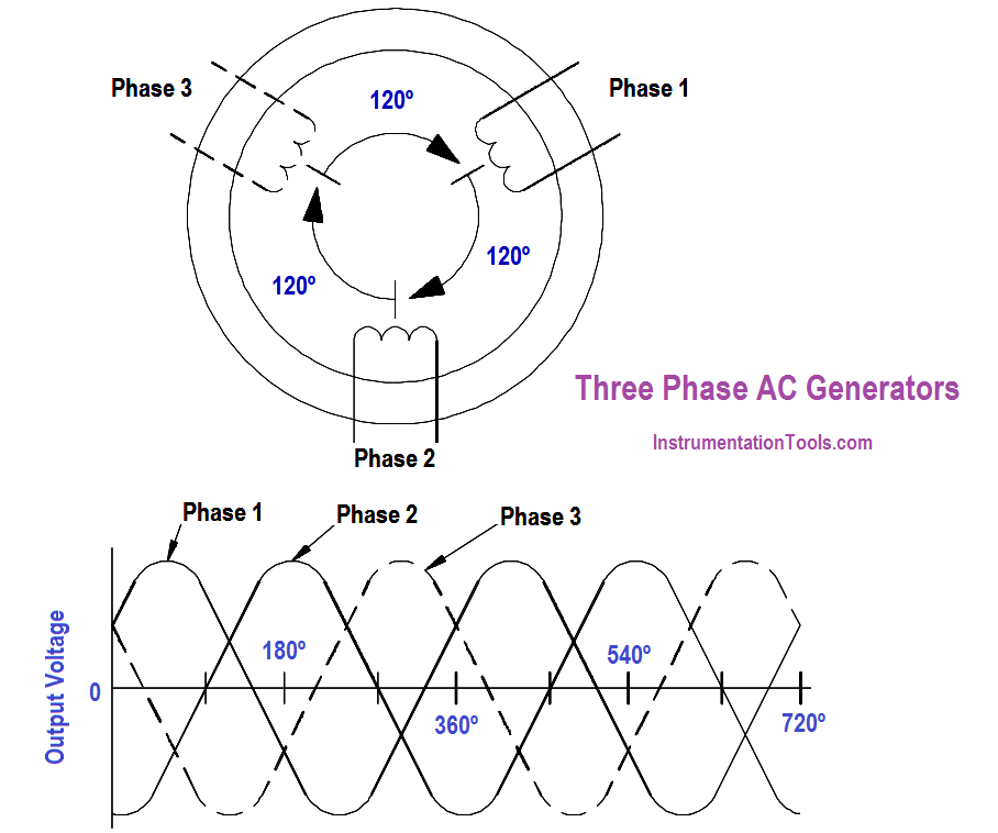
Figure : Stationary Armature 3φ Generator

AC Generator Connections

As shown in above Figure, there are six leads from the armature of a three-phase generator, and the output is connected to an external load. In actual practice, the windings are connected together, and only three leads are brought out and connected to the external load.

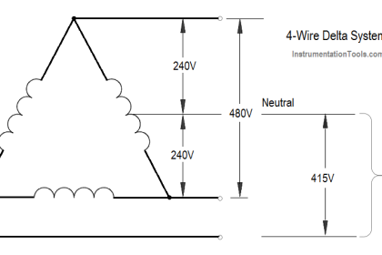
Two means are available to connect the three armature windings. In one type of connection, the windings are connected in series, or delta-connected (∆) (below Figure).

delta connected generator

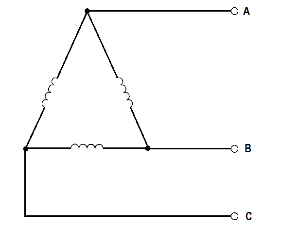
Figure : Delta Connection

In a delta-connected generator, the voltage between any two of the phases, called line voltage, is the same as the voltage generated in any one phase.

As shown in Below Figure, the three phase voltages are equal, as are the three line voltages. The current in any line is √3 times the phase current. You can see that a delta-connected generator provides an increase in current, but no increase in voltage.

Characteristics of a Delta-Connected Generator

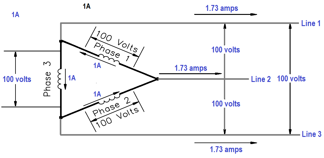
Figure : Characteristics of a Delta-Connected Generator

An advantage of the delta-connected AC generator is that if one phase becomes damaged or open, the remaining two phases can still deliver three-phase power. The capacity of the generator is reduced to 57.7% of what it was with all three phases in operation.

In the other type of connection, one of the leads of each winding is connected, and the remaining three leads are connected to an external load. This is called a wye connection (Y) (Below Figure).

Wye connected generator

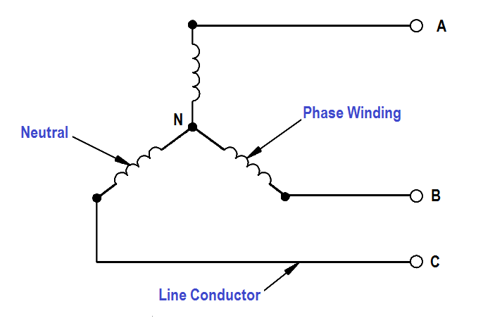
Figure : Wye Connection

The voltage and current characteristics of the wye-connected AC generator are opposite to that of the delta connection. Voltage between any two lines in a wye-connected AC generator is 1.73 (or ) √3 times any one phase voltage, while line currents are equal to phase currents. The wye-connected AC generator provides an increase in voltage, but no increase in current ( below Figure).

Characteristics of a Wye-Connected AC Generator

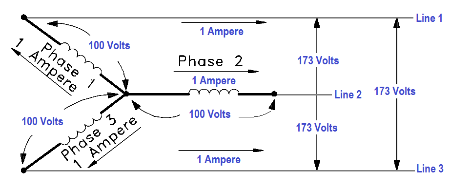
Figure : Characteristics of a Wye-Connected AC Generator

An advantage of a wye-connected AC generator is that each phase only has to carry 57.7% of line voltage and, therefore, can be used for high voltage generation.

Don't Miss Our Updates
Be the first to get exclusive content straight to your email.
We promise not to spam you. You can unsubscribe at any time.
Invalid email address
You've successfully subscribed !

Continue Reading

Shunt-Wound DC Generators
AC Generation Analysis : Effective Values, Phase Angle and Frequency
Three Phase Wattmeter
Three Phase Transformer Connections
Transformer Operation Under No-Load
Series Resistance
Share This Article
Facebook Whatsapp Whatsapp LinkedIn Copy Link
Share
Leave a Comment

Leave a Reply Cancel reply

Your email address will not be published. Required fields are marked *

Stay Connected

128.3kFollowersLike
69.1kFollowersFollow
210kSubscribersSubscribe
38kFollowersFollow

Categories

Explore More

Capacitive Time Constant
Series Short Circuit Faults
Impedance in RC Circuits
DC Machines Terminology
Synchronous Motors
Batteries Theory
Series – Parallel Circuit Analysis
Transformer Turns Ratio

Keep Learning

Cutaway View of Circuit Breaker

Low Voltage Air Circuit Breaker Principle

Using Kirchhoff’s Voltage Law to find Current with one Source

Applying Kirchhoff’s Voltage Law

Calculate Power in Parallel RCL Circuit

Calculate Power in Parallel RCL Circuit

Calculate Power in Series RL Circuit

Calculate Power in Series RL Circuit

Megger Circuit Diagram

Multimeter & Megger Principle

Parallel Circuit Parallel Current Calculations

Parallel Circuit Current Calculations

induction motor torque versus speed

Induction Motor Torque Versus Slip

Using Kirchhoff’s Voltage Law to find Current with Multiple Battery Sources

Kirchhoff’s Laws

Learn More

Advantages of Bundled Conductors in Transmission Lines

Advantages of Bundled Conductors in Transmission Lines

Pumping System in Industrial Automation

Basic Pumping System Application Used in Industrial Automation

Feedforward Control Questions & Answers

Feedforward Control Questions and Answers

failure rate of a component - 1

Failure rate and MTBF of Safety Instrumented Systems

How to Implement Ratio Control in this System

How to Implement Ratio Control in this System?

Top 100 Microcontrollers Project Ideas

Top 100 Microcontrollers Project Ideas

trip solenoid installed on a control valve appears

SIS Final Control Elements

Pull Cord Switch Principle

Pull Cord Switch Working Principle

Menu

  • About
  • Privacy Policy
  • Copyright

Quick Links

  • Learn PLC
  • Helping Hand
  • Part Time Job

YouTube Subscribe

Follow US
All rights reserved. Reproduction in whole or in part without written permission is prohibited.
Welcome Back!

Sign in to your account

Username or Email Address
Password

Lost your password?