A thermocouple consists of two pieces of dissimilar metals with their ends joined together (by twisting, soldering or welding). When heat is applied to the junction, a voltage, in the range of milli-volts (mV), is generated. A thermocouple is therefore said to be self-powered. Shown in Below Figure is a completed thermocouple circuit.
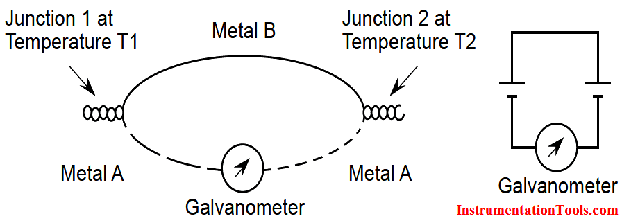
The voltage generated at each junction depends on junction temperature. If temperature T1 is higher than T2, then the voltage generated at Junction 1 will be higher than that at Junction 2. In the above circuit, the loop current shown on the galvanometer depends on the relative magnitude of the voltages at the two junctions.
In order to use a thermocouple to measure process temperature, one end of the thermocouple has to be kept in contact with the process while the other end has to be kept at a constant temperature. The end that is in contact with the process is called the hot or measurement junction. The one that is kept at constant temperature is called cold or reference junction. The relationship between total circuit voltage (emf) and the emf at the junctions is:
Circuit emf = Measurement emf – Reference emf
If circuit emf and reference emf are known, measurement emf can be calculated and the relative temperature determined.
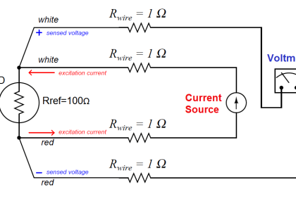
To convert the emf generated by a thermocouple to the standard 4-20 mA signal, a transmitter is needed. This kind of transmitter is called a temperature transmitter. Below Figure shows a simplified temperature transmitter connection.
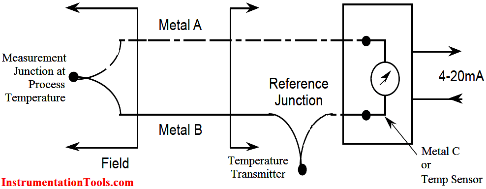
In Figure above, the temperature measurement circuit consists of a thermocouple connected directly to the temperature transmitter. The hot and
cold junctions can be located wherever required to measure the temperature difference between the two junctions.
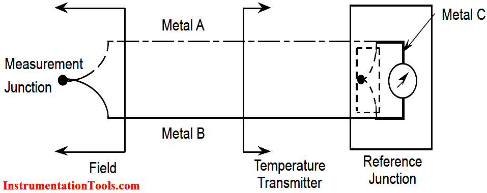
In most situations, we need monitor the temperature rise of equipment to ensure the safe operation. Temperature rise of a device is the operating temperature using ambient or room temperature as a reference. To accomplish this the hot junction is located in or on the device and the cold junction at the meter or transmitter as illustrated in Below figure.
Thermocouple Advantages and Disadvantages
Advantages:
- Thermocouples are used on most transformers. The hot junction is inside the transformer oil and the cold junction at the meter mounted on the outside. With this simple and rugged installation, the meter directly reads the temperature rise of oil above the ambient temperature of the location.
- In general, thermocouples are used exclusively around the turbine hall because of their rugged construction and low cost.
- A thermocouple is capable of measuring a wider temperature range than an RTD.
Disadvantages:
- If the thermocouple is located some distance away from the measuring device, expensive extension grade thermocouple wires or compensating cables have to be used.
- Thermocouples are not used in areas where high radiation fields are present (for example, in the reactor vault). Radioactive radiation (e.g., Beta radiation from neutron activation), will induce a voltage in the thermocouple wires. Since the signal from thermocouple is also a voltage, the induced voltage will cause an error in the temperature transmitter output.
- Thermocouples are slower in response than RTDs
- If the control logic is remotely located and temperature transmitters (milli-volt to milli- amp transducers) are used, a power supply failure will of course cause faulty readings.
Failure Modes:
- An open circuit in the thermocouple detector means that there is no path for current flow, thus it will cause a low (off-scale) temperature reading.
- A short circuit in the thermocouple detector will also cause a low temperature reading because it creates a leakage current path to the ground and a smaller measured voltage.
Thermal Wells / Thermo wells
The process environment where temperature monitoring is required, is often not only hot, but also pressurized and possibly chemically corrosive or radioactive. To facilitate removal of the temperature sensors (RTD and TC), for examination or replacement and to provide mechanical protection, the sensors are usually mounted inside thermal wells (Below Figure).
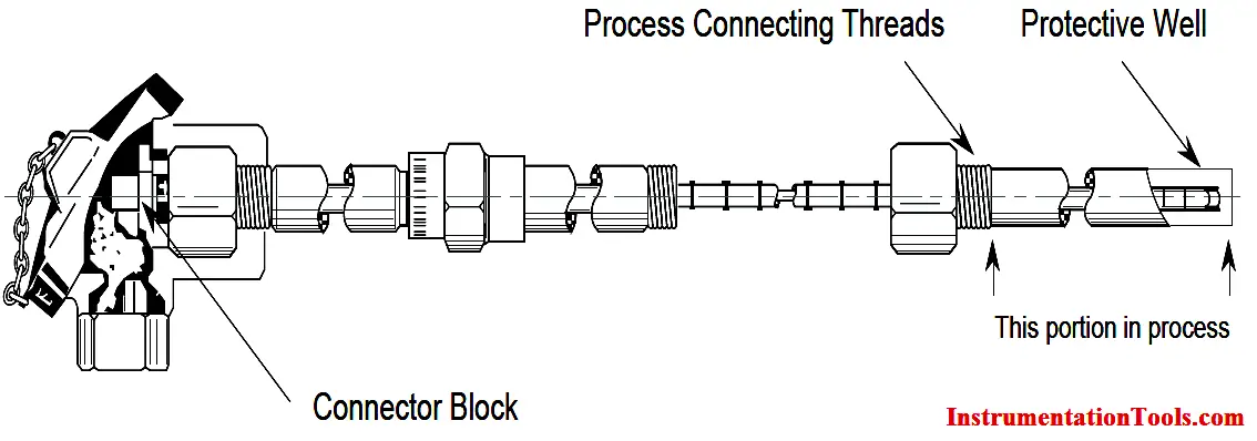
A thermal well is basically a hollow metal tube with one end sealed. It is usually mounted permanently in the pipe work. The sensor is inserted into it and makes contact with the sealed end.
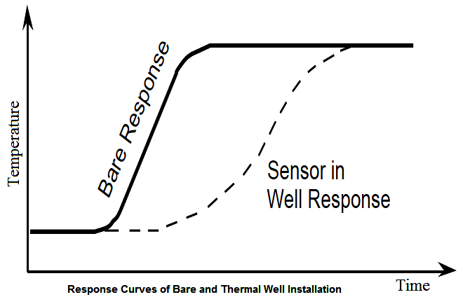
A drawback to thermal wells is their long response time because heat must be transferred through the well to the sensor. An example of the temperature response for bare and thermal well installed sensors is shown in Below Figure. Minimizing the air space between the sensor and the well, however, can decrease this thermal lag.


how is wake frequency calculated?
Sir, main stream temperature in field 530, junction box 530,dcs will checked 532.after connected in dcs temperature card in cable (1,2)the dcs reading show in less then 100
Hi, How you checked at Field, Junction Box & DCS ? For thermocouple > Check millivolt signals at all points and must be same. If found same value then check your DCS Card or its configuration. For testing > Connect this thermocouple in spare channel > configure with same config > Check reading. Also Check for any cable induction voltage..