Inst ToolsInst ToolsInst Tools
  • Courses
  • Automation
    • PLC
    • Control System
    • Safety System
    • Communication
    • Fire & Gas System
  • Instrumentation
    • Design
    • Pressure
    • Temperature
    • Flow
    • Level
    • Vibration
    • Analyzer
    • Control Valve
    • Switch
    • Calibration
    • Erection & Commissioning
  • Interview
    • Instrumentation
    • Electrical
    • Electronics
    • Practical
  • Q&A
    • Instrumentation
    • Control System
    • Electrical
    • Electronics
    • Analog Electronics
    • Digital Electronics
    • Power Electronics
    • Microprocessor
  • Request
Search
  • Books
  • Software
  • Projects
  • Process
  • Tools
  • Basics
  • Formula
  • Power Plant
  • Root Cause Analysis
  • Electrical Basics
  • Animation
  • Standards
  • 4-20 mA Course
  • Siemens PLC Course
Reading: Temperature Sensor calibration procedure
Share
Font ResizerAa
Inst ToolsInst Tools
Font ResizerAa
  • Courses
  • Design
  • PLC
  • Interview
  • Control System
Search
  • Courses
  • Automation
    • PLC
    • Control System
    • Safety System
    • Communication
    • Fire & Gas System
  • Instrumentation
    • Design
    • Pressure
    • Temperature
    • Flow
    • Level
    • Vibration
    • Analyzer
    • Control Valve
    • Switch
    • Calibration
    • Erection & Commissioning
  • Interview
    • Instrumentation
    • Electrical
    • Electronics
    • Practical
  • Q&A
    • Instrumentation
    • Control System
    • Electrical
    • Electronics
    • Analog Electronics
    • Digital Electronics
    • Power Electronics
    • Microprocessor
  • Request
Follow US
All rights reserved. Reproduction in whole or in part without written permission is prohibited.
Inst Tools > Blog > Calibration > Temperature Sensor calibration procedure

Temperature Sensor calibration procedure

Last updated: September 15, 2016 9:43 pm
Editorial Staff
Calibration Temperature Measurement
1 Comment
Share
2 Min Read
SHARE

Most instrument manuals state there is no calibration of the temperature sensor, but the temperature sensor must be checked to determine its accuracy. This accuracy check is performed at least once per year and the accuracy check date/information is kept with the instrument.

If the accuracy check date/information is not included with the instrument or the last check was over a year, the temperature sensor accuracy needs to be checked at the beginning of the sampling event. If the instrument contains multiple temperature sensors, each sensor must be checked.

This procedure is not normally perform in the field. If the instrument is obtained from a rental company, the rental company should performed the calibration check and include with the instrument documentation that it was performed.

Temperature-gauge-calibration

Calibration Procedure:

1. Fill a container with water and adjust the water temperature to below the water body’s temperature to be measured. Use ice or warm water to adjust the temperature.

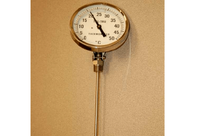
2. Place a thermometer that is traceable to the National Institute of Standards and Technology (NIST) and the instrument’s temperature sensor into the water. Wait for both temperature readings to stabilize.

3. Compare the two measurements. The instrument’s temperature sensor must agree with the reference thermometer measurement within the accuracy of the sensor (e.g.,±O.2°C). If the measurements do not agree, the instrument may not be working properly and the manufacturer needs to be consulted.Calibration-of-a-temperature-sensor

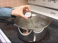
4. Adjust the water temperature to a temperature higher than the water body to be measured.

5. Compare the two measurements. The instrument’s temperature sensor must agree with the reference thermometer measurement within the accuracy of the sensor (e.g.,± 0.20 C). If the measurements do not agree, the instrument may not be working properly and the manufacturer needs to be consulted.

Don't Miss Our Updates
Be the first to get exclusive content straight to your email.
We promise not to spam you. You can unsubscribe at any time.
Invalid email address
You've successfully subscribed !

Continue Reading

Foundation Fieldbus Transmitter Calibration
Temperature Sensor Accessories
Thermal Imaging Temperature Measurement
Temperature Measurement Interview Questions
Thermocouple Calibration
Thermocouples Law of Intermediate Metals
Share This Article
Facebook Whatsapp Whatsapp LinkedIn Copy Link
Share
1 Comment
  • Mohan says:
    November 30, 2017 at 9:47 am

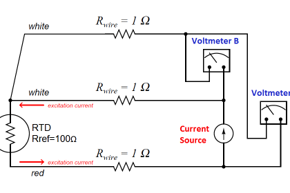
    What is 3 -Point Calibration especially for Thermcouples

    Reply

Leave a Reply Cancel reply

Your email address will not be published. Required fields are marked *

Stay Connected

128.3kFollowersLike
69.1kFollowersFollow
210kSubscribersSubscribe
38kFollowersFollow

Categories

Explore More

18 Temperature Sensors Fault Leads to Plant Shutdown
Seebeck Effect Theory
What is Bump Testing ?
Capacitance Level Sensor Principle, Limitations, Installation & Calibration
Electrical Standards
Resistance Temperature Detectors Troubleshooting Tips
General Specification of Thermowell
How to calculate the tolerance of a RTD sensor

Keep Learning

Bimetallic strip thermostat

Mechanical Temperature Measuring Sensors

Temperature Coefficient of Resistance

Temperature Coefficient of Resistance (α)

Temperature Sensors Questions

Questions on Thermocouple and Pyrometer

Filled-bulb Temperature Measurement

Filled-bulb Temperature Sensors

Single Position Calibration of Temperature Bath

Single Position Calibration of Temperature Bath

Three Wire RTD Circuit

What is a Three-wire RTD ?

Convert 2 wire RTD to 4 wire RTD Sensor

How to Convert 2 wire RTD into 3 or 4 wire RTD?

Sand Probe Functional Testing

Sand Probe Functional Testing

Learn More

What is a Thermostat

Thermostat – Types, Working Principle, Advantages, Applications

Ultrasonic Level Switch Principle

Ultrasonic Level Switch Principle

Sinking and Sourcing Devices Operation

PLC Sinking and Sourcing Explanation

What is Photoionization Detector (PID)

What is Photoionization Detector (PID)?

Nonlinear Control Systems

Constructing Phase-Trajectories

Electrical Torsion Meter

Electrical Torsion Meter Principle

PLC project for traffic signals automation

Complete PLC Project: Traffic Light Auto and Manual Automation

baffle-and-nozzle assembly

Pneumatic Sensing Elements

Menu

  • About
  • Privacy Policy
  • Copyright

Quick Links

  • Learn PLC
  • Helping Hand
  • Part Time Job

YouTube Subscribe

Follow US
All rights reserved. Reproduction in whole or in part without written permission is prohibited.
Welcome Back!

Sign in to your account

Username or Email Address
Password

Lost your password?