Inst ToolsInst ToolsInst Tools
  • Ask
  • Courses
  • Videos
  • Q & A
    • Interview
      • Instrumentation
      • Electronics
      • Electrical
      • Practical Questions
    • MCQ
      • Instrumentation MCQ
      • Electrical MCQ
      • Electronics MCQ
      • Control Systems MCQ
      • Analog Electronics MCQ
      • Digital Electronics MCQ
      • Power Electronics MCQ
      • Microprocessor MCQ
      • Multiple Choice Questions
  • EE
    • Electronics
      • Electronics Q & A
      • Electronic Basics
      • Electronic Devices & Circuits
      • Electronics Animation
      • Digital Electronics
    • Electrical
      • Electrical Basics
      • Electrical Q & A
      • Power Electronics
      • Electrical Machines
      • Electrical Animation
      • Power Systems
      • Switchgear & Protection
      • Transmission & Distribution
  • Measure
    • Control Valves
    • Calibration
    • Temperature
    • Pressure
    • Flow
    • Level
    • Analyzers
    • Switches
    • Vibration
    • Solenoid Valve
  • Control
    • PLC Tutorials
    • Control Systems
    • Safety Instrumented System (SIS)
    • Communication
    • Fire & Gas System
  • More
    • Design
    • Tools
    • Animation
    • Basics
    • Formulas
    • Standards
    • TextBooks
    • Common
    • Software
    • Excel Tools
    • Erection & Commissioning
    • Process Fundamentals
    • Videos
    • Books
Search
All rights reserved. Reproduction in whole or in part without written permission is prohibited.
Reading: Tanks Draining Control in PLC using Functional Block Diagram
Share
Notification Show More
Font ResizerAa
Inst ToolsInst Tools
Font ResizerAa
  • Courses
  • PLC Tutorials
  • Control Systems
Search
  • Ask
  • Courses
  • Videos
  • Q & A
    • Interview
    • MCQ
  • EE
    • Electronics
    • Electrical
  • Measure
    • Control Valves
    • Calibration
    • Temperature
    • Pressure
    • Flow
    • Level
    • Analyzers
    • Switches
    • Vibration
    • Solenoid Valve
  • Control
    • PLC Tutorials
    • Control Systems
    • Safety Instrumented System (SIS)
    • Communication
    • Fire & Gas System
  • More
    • Design
    • Tools
    • Animation
    • Basics
    • Formulas
    • Standards
    • TextBooks
    • Common
    • Software
    • Excel Tools
    • Erection & Commissioning
    • Process Fundamentals
    • Videos
    • Books
Follow US
All rights reserved. Reproduction in whole or in part without written permission is prohibited.
Inst Tools > Blog > PLC Tutorials > Tanks Draining Control in PLC using Functional Block Diagram

Tanks Draining Control in PLC using Functional Block Diagram

In PLC programming, we will learn tanks draining control for different products from two tanks using a functional block diagram.

Last updated: September 13, 2024 2:36 pm
Viral Nagda
PLC Tutorials
No Comments
Share
4 Min Read
SHARE

PLC programs for tanks are a very common part of industrial automation, due to their high frequency of usage in various systems. Tank level control needs to be done properly for efficient filling or draining operation.

Contents
Tanks Draining Control in PLCPLC Functional Block Diagram

Otherwise, the devices controlling the level will get pressure and result in some untoward incidents. In PLC programming, we will see a case on how to drain different products from two tanks using a functional block diagram. We will do it in FBD language, due to its high quality of troubleshooting and ease in writing.

Tanks Draining Control in PLC

Let us understand the problem and scenario first. There are two tanks. Each tank has a drain pump connected to it for draining the corresponding liquid. The outlet of both the pumps merge in a single header and fill a third tank. This means that the third tank will store a mixture of both the liquids.

The first tank will drain to a higher level, as compared to the second tank. So, the mixture will be a higher ratio of the first tank and a lower ratio in the second tank. The logic is such that only one pump will drain at a time, on the condition that the draining tank will be filled with desired level and the other tank will be empty with desired level.

PLC Functional Block Diagram

Now, let us write the PLC logic. The PLC IO’s are – two analog inputs (level of two tanks), and two digital outputs (two pumps). Refer to the below image.

The first part at the top, consisting of three blocks, will be used for the first pump. The second part in the bottom, consisting of three blocks, will be used for the second pump.

Tanks Draining Control in PLC using Functional Block Diagram

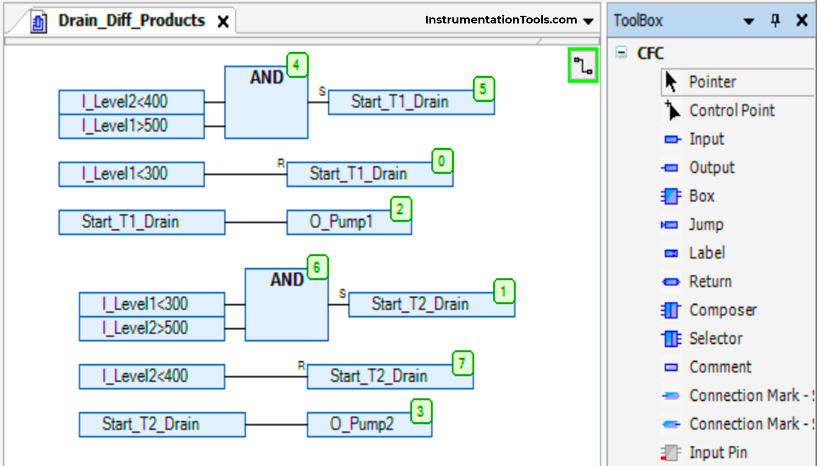
When the level of the first tank is above 500 liters and the level of the second tank is below 400 liters, then a bit named start_T1_drain will set and it will turn on the first pump. As long as the bit is set, the pump will remain on. When the level of the first tank goes below 300 liters, then that pump will turn off as we reset that bit.

Let us go to the second tank now. When the level of the second tank is above 500 liters and the level of the first tank is below 300 liters, then a bit named start_T2_drain will set and it will turn on the second pump. As long as the bit is set, the pump will remain on. When the level of the second tank goes below 400 liters, then that pump will turn off as we reset that bit.

This shows that the first tank drains around 200 liters, and the second tank drains around 100 liters; thus giving it a lower proportion. Tank filling logic is separate and not covered in this scope, as we are concerned with only draining.

The interlocking of both the tanks in the logic ensures that only one pump drains at a time, and that too only when there is sufficient level and the other tank is near empty. Thus, any foul program activity is prevented.

In this way, we saw how to write a PLC program for draining different products from two tanks using a functional block diagram.

Read Next:

  • Exhaust Fan Control: Example of PLC Timer Logic
  • Wood Sawing and Blower System: PLC Control
  • Automation Solutions Logic for Stairway Lighting
  • PID Controllers in Closed Loop Control Systems
  • PLC Programming for Pumping and Draining System
Don't Miss Our Updates
Be the first to get exclusive content straight to your email.
We promise not to spam you. You can unsubscribe at any time.
Invalid email address
You've successfully subscribed !
How to Add Security in InTouch SCADA?
Parts of PLC
1 to 8 Demultiplexer PLC ladder diagram
Functional Block Diagram in PLC for Oil and Water Process
WHILE DO Statement in SCL Language
Share This Article
Facebook Whatsapp Whatsapp LinkedIn Copy Link
Share
Leave a Comment

Leave a Reply Cancel reply

Your email address will not be published. Required fields are marked *

Stay Connected

128.3kFollowersLike
69.1kFollowersFollow
208kSubscribersSubscribe
38kFollowersFollow

Categories

Recent Comments

  • Guifty Shimica on Top Non-PLC Certification Courses for Automation Professionals
  • Guifty Shimica on Top Non-PLC Certification Courses for Automation Professionals
  • MIHARITSOA Aina Sitraka on Top Non-PLC Certification Courses for Automation Professionals
  • Vaishnavi on Free Instrumentation Course for Trainee Engineers

Related Articles

PLC Handbook

PLC Handbook

Automatic Car Washing Process using PLC Ladder Diagram

Automatic Car Washing using PLC

Studio 5000 Tutorial PLC Programming for Digital Alarms

Studio 5000 Tutorial: PLC Programming for Digital Alarms

Why 4-20 mA Current Signal is used instead of Voltage Signal

Troubleshooting a 4-20mA Current loop

Use Cryptographic checks for PLC

#5 PLC Best Practices – Cryptographic and Checksum Integrity Checks

PLC Program for Automatic Mixing Controlling in a Tank

PLC Program for Automatic Mixing Control in a Tank

Demo of a SCADA Software – Level Control System

PLC Program for Car Parking

PLC Program for Entry and Exit Control of Car Parking

More Articles

Level Instruments

Level Instruments General Specifications

Structured Text PLC Program for Measuring Event Duration

Structured Text PLC Program for Measuring Event Duration

Relay Parts

NO vs NC Contact

Instrumentation Project Engineers Interview Questions

Instrumentation Project Engineer Interview Questions

Industrial PLC Communication Network

Basics of Industrial Communication Networks

temperature compensation circuit for PMMC

PMMC Temperature Compensation

ANSI Class Relates to PSI

How ANSI Class Relates to PSI ?

Displacement Transducers Objective Questions

Displacement Transducers Objective Questions

Follow US
All rights reserved. Reproduction in whole or in part without written permission is prohibited.
Welcome Back!

Sign in to your account

Username or Email Address
Password

Lost your password?