Inst ToolsInst ToolsInst Tools
  • Ask
  • Courses
  • Videos
  • Q & A
    • Interview
      • Instrumentation
      • Electronics
      • Electrical
      • Practical Questions
    • MCQ
      • Instrumentation MCQ
      • Electrical MCQ
      • Electronics MCQ
      • Control Systems MCQ
      • Analog Electronics MCQ
      • Digital Electronics MCQ
      • Power Electronics MCQ
      • Microprocessor MCQ
      • Multiple Choice Questions
  • EE
    • Electronics
      • Electronics Q & A
      • Electronic Basics
      • Electronic Devices & Circuits
      • Electronics Animation
      • Digital Electronics
    • Electrical
      • Electrical Basics
      • Electrical Q & A
      • Power Electronics
      • Electrical Machines
      • Electrical Animation
      • Power Systems
      • Switchgear & Protection
      • Transmission & Distribution
  • Measure
    • Control Valves
    • Calibration
    • Temperature
    • Pressure
    • Flow
    • Level
    • Analyzers
    • Switches
    • Vibration
    • Solenoid Valve
  • Control
    • PLC Tutorials
    • Control Systems
    • Safety Instrumented System (SIS)
    • Communication
    • Fire & Gas System
  • More
    • Design
    • Tools
    • Animation
    • Basics
    • Formulas
    • Standards
    • TextBooks
    • Common
    • Software
    • Excel Tools
    • Erection & Commissioning
    • Process Fundamentals
    • Videos
    • Books
Search
All rights reserved. Reproduction in whole or in part without written permission is prohibited.
Reading: Tank Level Control in PLC
Share
Notification Show More
Font ResizerAa
Inst ToolsInst Tools
Font ResizerAa
  • Courses
  • PLC Tutorials
  • Control Systems
Search
  • Ask
  • Courses
  • Videos
  • Q & A
    • Interview
    • MCQ
  • EE
    • Electronics
    • Electrical
  • Measure
    • Control Valves
    • Calibration
    • Temperature
    • Pressure
    • Flow
    • Level
    • Analyzers
    • Switches
    • Vibration
    • Solenoid Valve
  • Control
    • PLC Tutorials
    • Control Systems
    • Safety Instrumented System (SIS)
    • Communication
    • Fire & Gas System
  • More
    • Design
    • Tools
    • Animation
    • Basics
    • Formulas
    • Standards
    • TextBooks
    • Common
    • Software
    • Excel Tools
    • Erection & Commissioning
    • Process Fundamentals
    • Videos
    • Books
Follow US
All rights reserved. Reproduction in whole or in part without written permission is prohibited.
Inst Tools > Blog > PLC Tutorials > Tank Level Control in PLC

Tank Level Control in PLC

Last updated: March 4, 2021 2:14 pm
Editorial Staff
PLC Tutorials
2 Comments
Share
3 Min Read
SHARE

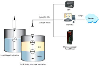
Design a PLC program to control the liquid level in a tank. A level transmitter is used to measure the tank level into a standard current signal from 4 to 20mA as illustrated in the below process diagram.

Contents
Tank Level Control in PLCPLC Program LogicScaling Tabular Column:PLC Programming for Tank Level ControlPLC Program DescriptionRung 0000:Rung 0001:Rung 0002:Rung 0003:Rung 0004:Rung 0005 & 0006:Rung 0007 & 0008:Conclusion

Tank Level Control in PLC

Tank Level Control in PLC

PLC Program Logic

  1. The agitator motor is to be started and stopped by a pushbutton station.
  2. The solenoid valves are to be open (Energized) when the agitator is running.
  3. Pump N0.1 starts at the 75% liquid level and stops at the 25% level. The pump will run only if the agitator is running.
  4. On a high-level alarm (Tank 90%), an alarm light will come ON and stay on even if the tank level drops. An operator must press the reset button to turn off the light. On the high-level alarm, both the solenoid valve will also close (de-energize).
  5. A low-level alarm light shall be provided (Tank 10%), similar to the high level, and reset using the same pushbutton.

Scaling Tabular Column:

Level Transmitter Readings in PLC

PLC Programming for Tank Level Control

PLC Programming for Tank Level Control
PLC Interface for Level Transmitter

PLC Program Description

Rung 0000:

Start/Stop PB latched with memory B3:0/0.

Rung 0001:

B3:0/0 enabled to turn on agitator (O: 0/0), Solenoid valve 1 (O:0/1) and Solenoid valve 2 (O:0/2).

Rung 0002:

Scaling block is used, Level transmitter gives output in mA (N7:0), to convert that into PLC range (N7:1), and scaling block is used.

Refer to the above tabular column for a respective range of values.

Rung 0003:

According to the program logic, we need to turn on the PUMP (O:0/3) at tank reaching 75%

And the pump still is in ON condition up to 25%, so comparator blocks are used to get this condition.

Agitator motor contact also connected in series as mentioned in program logic.

Rung 0004:

Memory coil connected to turn ON pump motor output.

Rung 0005 & 0006:

High-level alarm should turn ON when tank reaching 90% and should not turn off until alarm reset (I:0/2) is pressed.

Greater than or equal block is used to compare the real scaling value(N7:1) and register value.

Rung 0007 & 0008:

Low-level alarm should turn ON when tank reaching 10% and should not turn off until alarm reset (I:0/2) is pressed.

Less than or equal block is used to compare the real scaling value(N7:1) and register value.

Conclusion

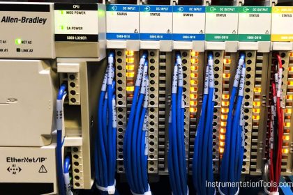
We can use this example to understand the programming logic in Allen Bradley Programmable Logic Controller (PLC).

Author: Hema Sundaresan

If you liked this article, then please subscribe to our YouTube Channel for PLC and SCADA video tutorials.

You can also follow us on Facebook and Twitter to receive daily updates.

Read Next:

  • Motor control in Ladder logic
  • Conveyor Ladder Logic Program
  • Function Block Programming
  • Operator Interface for SCADA
  • Control Instructions in PLC
Don't Miss Our Updates
Be the first to get exclusive content straight to your email.
We promise not to spam you. You can unsubscribe at any time.
Invalid email address
You've successfully subscribed !
How to import GSD files into the TIA Portal? – Siemens PLC
PLC Raw Count Calculation for Pressure Transmitter
PLC Sequencer Instruction with Example
PLC Program for Control Valve Scaling
Schneider Electric: Car Parking System with Calculations in PLC
Share This Article
Facebook Whatsapp Whatsapp LinkedIn Copy Link
Share
2 Comments
  • Sunil yadav says:
    June 30, 2022 at 6:13 am

    sir i having level sensor problems in delta AS228R how can i solved this problem plz reply me

    Reply
  • Mr. unknown says:
    October 26, 2023 at 11:45 am

    Ya you can solve it

    Reply

Leave a Reply Cancel reply

Your email address will not be published. Required fields are marked *

Stay Connected

128.3kFollowersLike
69.1kFollowersFollow
208kSubscribersSubscribe
38kFollowersFollow

Categories

Recent Comments

  • Guifty Shimica on Top Non-PLC Certification Courses for Automation Professionals
  • Guifty Shimica on Top Non-PLC Certification Courses for Automation Professionals
  • MIHARITSOA Aina Sitraka on Top Non-PLC Certification Courses for Automation Professionals
  • Vaishnavi on Free Instrumentation Course for Trainee Engineers

Related Articles

Connect PLC with SCADA System via OPC UA

How to Connect PLC with SCADA System via OPC UA?

PLC Automatic Irrigation System Ladder Logic Project

PLC Automatic Irrigation System

Structured Text Selector Machine Logic

Write a PLC Program for Selector Machine using Structured Text

Siemens PLC

Five Types of PLC Programming languages

What is NEST loading in DCS

What is Nest Loading? – DCS and PLC Control Systems

PLC Program for Blinking Lamp on 5 Seconds Interval

PLC Program for Blinking Lamp on 5 Seconds Interval

Fail Safe Switch Circuit

Basics of Fail-safe Circuits

PLC Program for Sequential Motor Control

PLC Program for Sequential Motor Control

More Articles

Analytical Measurement Multiple Choice Questions

Analytical Measurement Multiple Choice Questions

compressor emergency shutdown system

Compressor Emergency Shutdown Root Cause Analysis

Transmission Control Protocol

Difference Between TCP and UDP

Digital Electronics Multiple Choice Questions

Introduction of Arithmetic Operation

Control Systems Questions & Answers

Control Systems Objective Questions & Answers – Set 5

Free Download PLC Book

Free Download Programmable Logic Controller (PLC) Book

DP Transmitter Block and Bleed Valve

DP Transmitter Block and Bleed Valves

Simatic Prosave HMI

How to Backup and Restore from Simatic Prosave HMI?

Follow US
All rights reserved. Reproduction in whole or in part without written permission is prohibited.
Welcome Back!

Sign in to your account

Username or Email Address
Password

Lost your password?