This article is about a T-junction traffic control system with the help of a PLC ladder logic using a comparator for lights operation.
T-Junction Traffic Control System
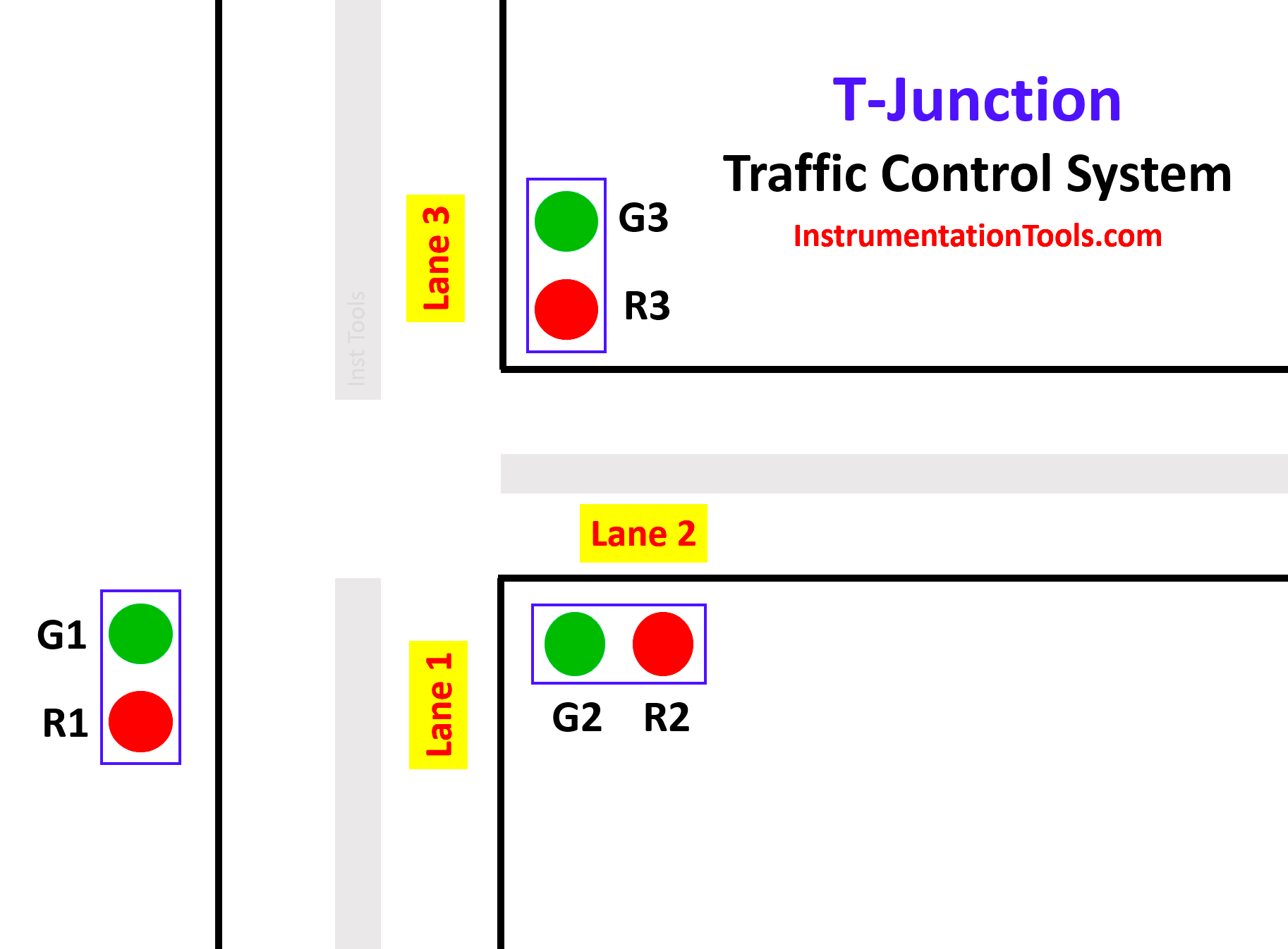
The function of the T-junction traffic control system consists of three groups of segments. By the logic of comparator operation, we control the Traffic lights system.
- First segment:
In the first segment, lane 1 traffic is allowed and lane 2 and lane 3 are stopped. Here in this segment, the green light (Green 1) of lane 1 glows, and red lights (Red 2) of lane 2 and (Red 3) of lane 3 glow. This period continues for fifteen seconds.
- Second segment:
In the second segment, lane 2 traffic is allowed and lane 1 and lane 3 are stopped. Here in this segment, the green light (Green 2) of Lane 2 glows, and the red lights (Red 1) of Lane 1 and (Red 3) of Lane 3 glows. This period continues for fifteen seconds.
- Third segment:
In the third segment, lane 3 traffic is allowed and lane 1 and lane 2 are stopped. Here in this segment, the green light (Green 3) of Lane 3 glows, and the red lights (Red 1) of Lane 1 and (Red 2) of Lane 2 glow. This period continues for fifteen seconds.
After the execution of all three segments, the sequence of operations again starts and repeats continuously.
Try PLC Courses – Advanced PLC Training
Description of Inputs and Outputs
In this PLC project, we used 2 Inputs, 6 Outputs, 2 Memory, and 1 On Delay Timer.
| S.No | Symbol | Description |
| 1 | I 0.0 | START |
| 2 | I 0.1 | STOP |
| 3 | M 0.0 | MEMORY |
| 4 | M 0.1 | MEMORY 1 |
| 5 | Q 0.0 | GREEN 1 |
| 6 | Q 0.1 | RED 1 |
| 7 | Q 0.2 | GREEN 2 |
| 8 | Q 0.3 | RED 2 |
| 9 | Q 0.4 | GREEN 3 |
| 10 | Q 0.5 | RED 3 |
| 11 | DB1 | ON DELAY TIMER |
PLC Programming and its Explanation
1. When the START (I 0.0) Button is pressed, MEMORY (M 0.0) is energized. This M 0.0 is the main memory used to execute all the processes in the program. Since it is latched, it will be in energized state only. If STOP ( I 0.1) is pressed whole process will get stopped at any time.
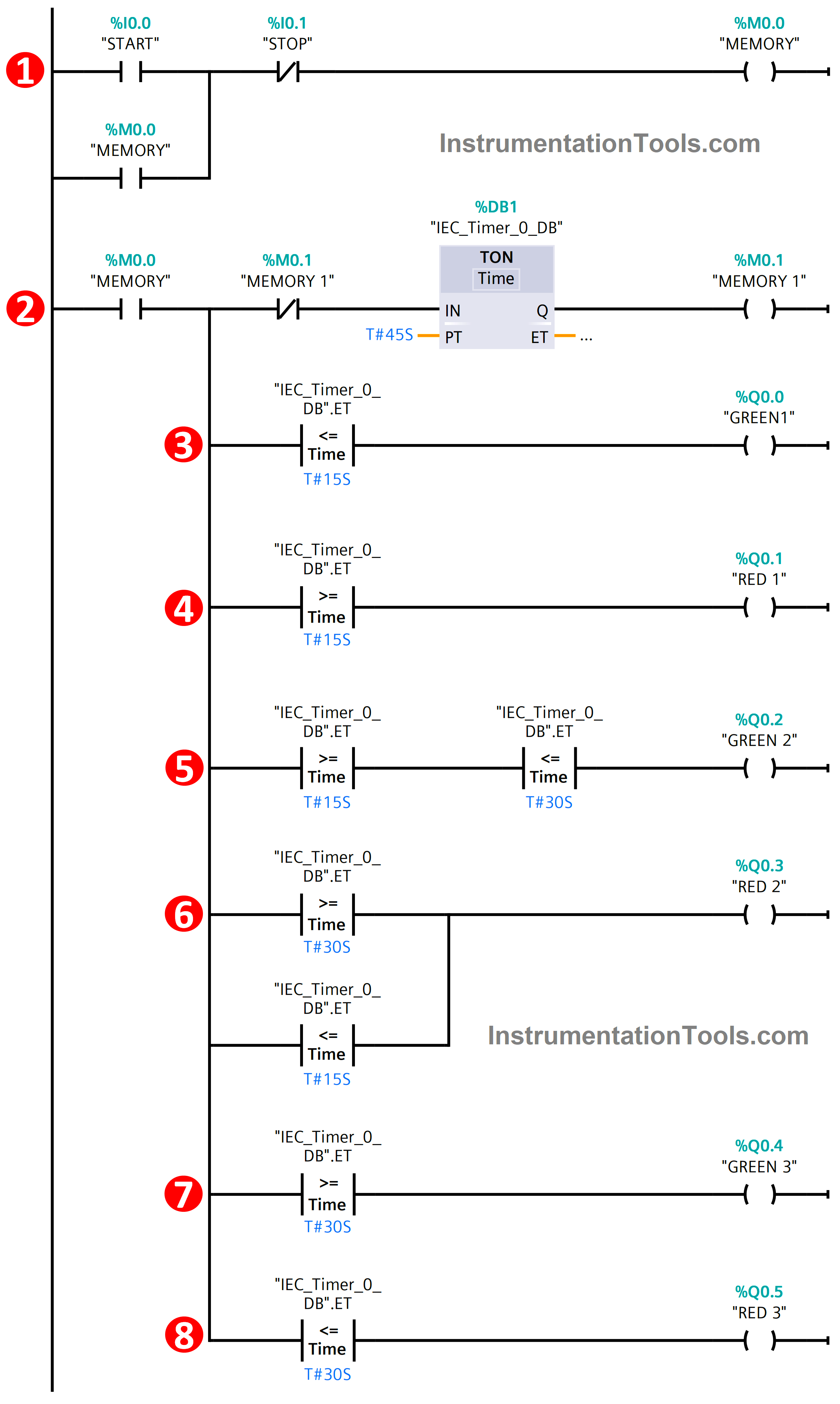
2. Once MEMORY is energized, it will switch on the TIMER DB1 which controls the timing of the Traffic Junction. In this timer, we set the Pre-set time of 45 seconds. Once the timer achieves the pre-set time which energizes the MEMORY 1 (M 0.1) and this M 0.1 also resets the timer as per the logic and runs the cycle continuously.
3. Next, the comparator plays a major role in controlling the traffic junction. Firstly, the Output GREEN 1 (Q 0.0) is turned on as per the logic. Here we used Less than or Equal to the comparator. In this logic, Q0.0 will be in the ON state from 0 seconds to 15 seconds. After that, it will be going to OFF state
4. Next for output RED 1 (Q0.1), we used Greater than or Equal to function. Q0.1 will be in the ON state from 15 seconds to 45 seconds. It will be in the OFF state when Q0.0 is in the ON state.
5. Then for output GREEN 2 (Q0.2), we used both Less than or Equal to and Greater than or Equal to for this output. Both the comparator functions were connected in series logic connection with the output. In this Q0.2 will be in the ON state from 16 seconds to 30 seconds as per the condition.
6. Next for output RED 2 (Q0.3), we also used both Less than or Equal to and Greater than or Equal to function for performing the operation. Comparators were connected in parallel connection with the output. This output will be in the ON state from 0 seconds to 15 seconds and 30 seconds to 45 seconds. In between 15 seconds, it will be in the OFF state only since at that time Q0.2 is in the ON state.
7. Then for the last GREEN 3 output (Q0.4), we used Greater than or Equal to function. As per the conditional logic, it will be in an ON state from 30 seconds to 45 seconds. Before this timing, it will be in an OFF state.
8. Finally, the RED 3 output (Q0.5). Here we used Less than or Equal to function for executing the PLC logic. It will be in the ON state from 0 seconds to 30 seconds after that it will be in the OFF state.
Conclusion
So, in this way, the given T-Junction Traffic control is executed by the comparator function with the PLC logic. We can control the traffic logic with the help of PLC logic in many ways & this is also one of the ways in that.
If are you interested to learn another approach for traffic light control using PLC, then watch the below video.
If you liked this article, then please subscribe to our YouTube Channel for Instrumentation, Electrical, PLC, and SCADA video tutorials.
You can also follow us on Facebook and Twitter to receive daily updates.
Read Next:
- PLC Restrict Data Interfaces
- Use PLC Flags as Integrity Checks
- Offline and Online UPS Systems
- Diagnostic Buffer for SIEMENS PLC
- Modbus Driver for SCADA System