Inst ToolsInst ToolsInst Tools
  • Courses
  • Automation
    • PLC
    • Control System
    • Safety System
    • Communication
    • Fire & Gas System
  • Instrumentation
    • Design
    • Pressure
    • Temperature
    • Flow
    • Level
    • Vibration
    • Analyzer
    • Control Valve
    • Switch
    • Calibration
    • Erection & Commissioning
  • Interview
    • Instrumentation
    • Electrical
    • Electronics
    • Practical
  • Q&A
    • Instrumentation
    • Control System
    • Electrical
    • Electronics
    • Analog Electronics
    • Digital Electronics
    • Power Electronics
    • Microprocessor
  • Request
Search
  • Books
  • Software
  • Projects
  • Process
  • Tools
  • Basics
  • Formula
  • Power Plant
  • Root Cause Analysis
  • Electrical Basics
  • Animation
  • Standards
  • 4-20 mA Course
  • Siemens PLC Course
Reading: Synchronous Motors
Share
Font ResizerAa
Inst ToolsInst Tools
Font ResizerAa
  • Courses
  • Design
  • PLC
  • Interview
  • Control System
Search
  • Courses
  • Automation
    • PLC
    • Control System
    • Safety System
    • Communication
    • Fire & Gas System
  • Instrumentation
    • Design
    • Pressure
    • Temperature
    • Flow
    • Level
    • Vibration
    • Analyzer
    • Control Valve
    • Switch
    • Calibration
    • Erection & Commissioning
  • Interview
    • Instrumentation
    • Electrical
    • Electronics
    • Practical
  • Q&A
    • Instrumentation
    • Control System
    • Electrical
    • Electronics
    • Analog Electronics
    • Digital Electronics
    • Power Electronics
    • Microprocessor
  • Request
Follow US
All rights reserved. Reproduction in whole or in part without written permission is prohibited.
Inst Tools > Blog > Electrical Theory > Synchronous Motors

Synchronous Motors

Last updated: August 6, 2018 9:16 pm
Editorial Staff
Electrical Theory
No Comments
Share
1 Min Read
SHARE

Synchronous motors are like induction motors in that they both have stator windings that produce a rotating magnetic field. Unlike an induction motor, the synchronous motor is excited by an external DC source and, therefore, requires slip rings and brushes to provide current to the rotor.

In the synchronous motor, the rotor locks into step with the rotating magnetic field and rotates at synchronous speed. If the synchronous motor is loaded to the point where the rotor is pulled out of step with the rotating magnetic field, no torque is developed, and the motor will stop.

A synchronous motor is not a self-starting motor because torque is only developed when running at synchronous speed; therefore, the motor needs some type of device to bring the rotor to synchronous speed.

Synchronous Motor Principle

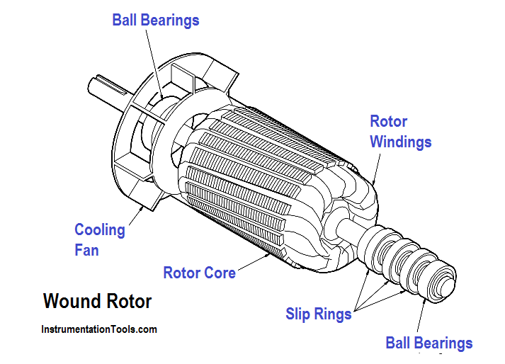
Figure : Wound Rotor

Synchronous motors use a wound rotor. This type of rotor contains coils of wire placed in the rotor slots. Slip rings and brushes are used to supply current to the rotor. (as shown in above Figure).

Don't Miss Our Updates
Be the first to get exclusive content straight to your email.
We promise not to spam you. You can unsubscribe at any time.
Invalid email address
You've successfully subscribed !

Continue Reading

Classification of Transformers
Single Phase Power Wiring Schemes
Series Open Circuit Faults
Series and Parallel Capacitors
Half-Wave Rectifier Circuit
Transformer Losses and Efficiency
Share This Article
Facebook Whatsapp Whatsapp LinkedIn Copy Link
Share
Leave a Comment

Leave a Reply Cancel reply

Your email address will not be published. Required fields are marked *

Stay Connected

128.3kFollowersLike
69.1kFollowersFollow
210kSubscribersSubscribe
38kFollowersFollow

Categories

Explore More

Reading Electrical Schematics
Transformer Impedance Ratio
DC Motor Connections
Unbalanced 3 Phase Loads
Three Phase Systems
Discharge and Charging of Lead-Acid Battery
Applying Kirchhoff’s Current Law
Battery Operation : Series and Parallel

Keep Learning

current division Formula for Resistor Circuit

Current Division

Carbon Atom

What is Electricity ?

circuit breaker principle

What is a circuit breaker ?

Ammeter with Shunt

Ammeter

Ground Detector Lamp Method Principle

Ground Detector Principle

Transformer Operation Under No-Load

Transformer Operation Under No-Load

Simple RC Circuit

Impedance in RC Circuits

Transformer Tap changer

Transformer Mutual Induction

Learn More

Omron PLC painting program

Product Painting PLC Program using Omron CX-Programmer

Oscillators and Signal Generators Objective Questions

Oscillators and Signal Generators Objective Questions

Top 10 Facts about HART Technology

Top 10 Facts about HART Technology

Read Temperature in PLC

PLC Program to Read Temperature in PLC

Digital Electronics Multiple Choice Questions

Parity Checkers Objective Questions

Pneumatic Temperature Transmitter with Sensor Principle

Pneumatic Temperature Transmitter with Sensor Principle

Two Electrode Conductivity Probes

Two Electrode Conductivity Probes Principle

Self Actuated Pressure Control Valve Principle

Self Actuated Pressure Control Valve Principle

Menu

  • About
  • Privacy Policy
  • Copyright

Quick Links

  • Learn PLC
  • Helping Hand
  • Part Time Job

YouTube Subscribe

Follow US
All rights reserved. Reproduction in whole or in part without written permission is prohibited.
Welcome Back!

Sign in to your account

Username or Email Address
Password

Lost your password?