Inst ToolsInst ToolsInst Tools
  • Courses
  • Automation
    • PLC
    • Control System
    • Safety System
    • Communication
    • Fire & Gas System
  • Instrumentation
    • Design
    • Pressure
    • Temperature
    • Flow
    • Level
    • Vibration
    • Analyzer
    • Control Valve
    • Switch
    • Calibration
    • Erection & Commissioning
  • Interview
    • Instrumentation
    • Electrical
    • Electronics
    • Practical
  • Q&A
    • Instrumentation
    • Control System
    • Electrical
    • Electronics
    • Analog Electronics
    • Digital Electronics
    • Power Electronics
    • Microprocessor
Search
  • Books
  • Software
  • Projects
  • Process
  • Tools
  • Basics
  • Formula
  • Power Plant
  • Root Cause Analysis
  • Electrical Basics
  • Animation
  • Standards
  • 4-20 mA Course
  • Siemens PLC Course
Reading: Superheated Steam Temperature Control System
Share
Notification Show More
Font ResizerAa
Inst ToolsInst Tools
Font ResizerAa
  • Courses
  • Design
  • PLC
  • Interview
  • Control System
Search
  • Courses
  • Automation
    • PLC
    • Control System
    • Safety System
    • Communication
    • Fire & Gas System
  • Instrumentation
    • Design
    • Pressure
    • Temperature
    • Flow
    • Level
    • Vibration
    • Analyzer
    • Control Valve
    • Switch
    • Calibration
    • Erection & Commissioning
  • Interview
    • Instrumentation
    • Electrical
    • Electronics
    • Practical
  • Q&A
    • Instrumentation
    • Control System
    • Electrical
    • Electronics
    • Analog Electronics
    • Digital Electronics
    • Power Electronics
    • Microprocessor
Follow US
All rights reserved. Reproduction in whole or in part without written permission is prohibited.
Inst Tools > Blog > Process Fundamentals > Superheated Steam Temperature Control System

Superheated Steam Temperature Control System

In this article, we will learn the operation of superheated steam temperature control system in a boiler.

Last updated: September 28, 2022 3:31 pm
Shiv Kumar
Process Fundamentals
No Comments
Share
6 Min Read
SHARE

In this article, we will see about the Super Heater, and How the Steam Temperature is controlled in the Super Heater.

Contents
What is a Superheater?What is Desuperheater?Stages of Superheater used in BoilerSuperheated Steam Temperature Control System
  • In the Boiler, The Superheater is the most important device for generating Steam,
  • It is generally the Integral part of the boiler.
  • The purpose of a Superheater is to increase the Temperature of the Saturated Steam without raising its pressure.
  • This is placed in the path of Hot Flue gases from the furnace.
  • The Heat Liberated by these flue gases is used to superheat the steam to the Required Boilers Design temperature.

What is a Superheater?

A Superheater is a set of vertical tubes connected between the headers to minimize the pressure drop of the Superheated Steam.

One Header is connected to the Steam Drum to receive the Saturated Steam and the Other Header is connected to the outlet of the Main Steam Stop valve (MSSV).

What is Desuperheater?

 The Process of Controlling the temperature of the Super-heated Steam by spraying water of High Purity through the Spray Nozzles. The Device Used is called De-Superheater or Attemperator.

Stages of Superheater used in Boiler

 In a Boiler, the Super Heater is Having 3 Stages,

  • Primary Superheater (PSH),
  • Intermediate Superheater (ISH),
  • Secondary Superheater  (SSH),
Superheated  Steam Temperature Control System

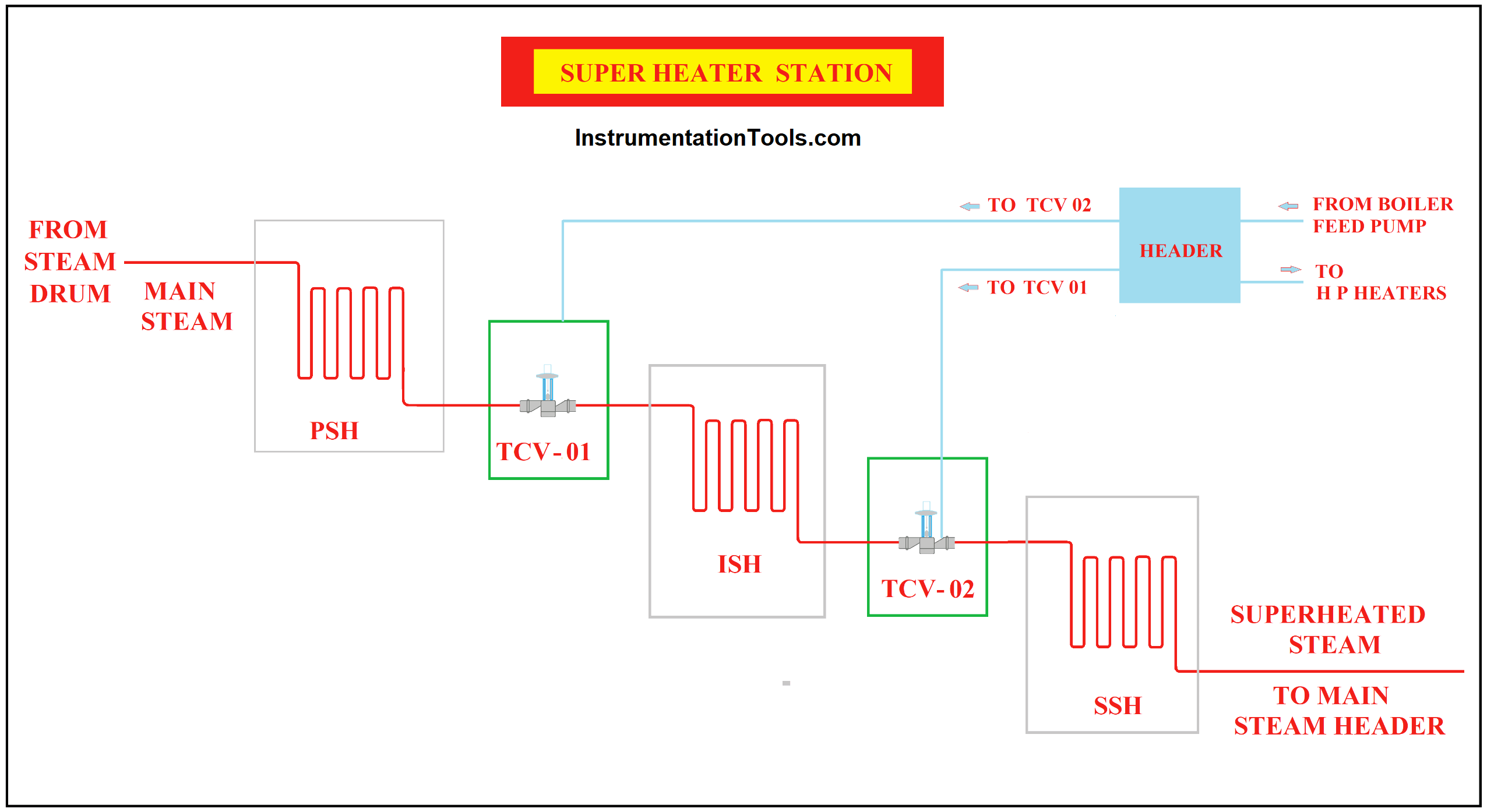
To Generate the Main Steam of Desired Temperature, we use Two Desuperheating Stations, with Two Temperature Loop Control systems that exist between the stages of the Superheater.

  • The First Loop of  Desuperheating is between Primary Superheater and Intermediate Superheater, Temperature Control Valve  (TCV-01)
  • The second Loop of Desuperheating is between Intermediate Superheater and Secondary Superheater, with Temperature Control Valve  (TCV-02)

In Boiler the Stem Path is from Steam Drum to the Secondary Superheater,

Initially, the Temperature of the Main Steam to be controlled is sent to Primary Superheater (PSH), then to Intermediate Superheater (ISH), and finally to the Secondary Superheater (SSH) through Temperature Control Valve.

The Steam Temperature at Various Stages of the Superheater is as below,

  • The Temperature at the outlet of the Primary Superheater (PSH) is 350 oC
  • The Temperature at the outlet of the Intermediate Superheater (ISH) is 440 oC
  • The Temperature at the outlet of the Secondary Superheater (ISH) is 530 oC

`The outlet of the Secondary Superheater (SSH) is the Main Steam at a designed boiler Steam Parameter, is Sent to Turbine and to PRDS through Steam header.

In This method, the Attemperation spray water of high purity is introduced into the Superheated Steam line through a Spray Nozzle.

The Water rapidly evaporates and mixes with the Steam to reduce the Temperature.

This system provides a Quick Response and Sensitive means of Temperature control of the main steam.

The Steam Temperature is controlled using two Temperature Loop Control systems maintaining a constant temperature at the outlets of the Superheater.

Superheated Steam Temperature Control System

The Steam Temperature control at each stage is the same but the Temperature Set Point is Different in Both Loops.

The Attemperation water is the Boiler feed water that is taken from the feed pump itself.

The Attemperation water of High Purity is sprayed at a high velocity through Spray nozzles and at an adequate quantity on the Desuperheating Station. To reduce the temperature of superheated steam to the required temperature of 350oC in the First loop and 440oC in the Second loop.

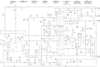
The Temperature element (TE) senses the Outlet Steam Temperature and gives a proportional current signal to the PID controller via the Temperature transmitter (TT).

The PID controller then compares the Process Variable (Measured Value) received from the Temperature transmitter (TT) with a given SetPoint (SP), generates an error signal, and is then given to the valve positioner, which determines the position of the Temperature Control Valve (TCV).

This  valve opens accordingly and sprays atomized water through the spray nozzle until the steam temperature reaches the set value, and re-closes to prevent the further spray of water after normal conditions have been restored,

i.e. Process Variable (PV) must be equal to SetPoint (SP).

PV=SP

The Components Used in both Temperature Loop Control Systems are.

  1. Temperature Control valves (TCV 01 and 02)
  2. Controllers
  3. Temperature Element
  4. Temperature Transmitter

The Boiler has the Following Specifications:

  • Boiler Make:   ISGEC Boiler
  • Main Steam temperature: 530 Degree Celsius
  • Main Steam  Pressure: 110 Kg/cm2
  • Main Steam Flow: 120 TPH.

Note: The temperature and pressure values will vary depending on the boiler type and plant.

Don't Miss Our Updates
Be the first to get exclusive content straight to your email.
We promise not to spam you. You can unsubscribe at any time.
Invalid email address
You've successfully subscribed !

Continue Reading

What is Hot Water Recirculation Loop? Advantages & Design
Desuperheater Design
Heat Exchanger Root Cause Analysis (RCA)
Process Control High Level Alarm Fault Analysis
Process Control Loop Testing
Reciprocating Compressors
Share This Article
Facebook Whatsapp Whatsapp LinkedIn Copy Link
Share
Leave a Comment

Leave a Reply Cancel reply

Your email address will not be published. Required fields are marked *

Stay Connected

128.3kFollowersLike
69.1kFollowersFollow
208kSubscribersSubscribe
38kFollowersFollow

Categories

Explore More

Filters in Compressors
CO2 Stripper Collapsed Internals Revamp
What is a Circulating Pump?
What is EDI in a Water Treatment Plant? – Electro deionization
Centrifugal Compressors
Hydraulic System
Plant Air Storage Tank Pressure Fluctuations Root Cause Analysis
What is a Dosing Pump? – Types, Advantages, Applications

Keep Learning

desuperheater

Concept of Desuperheater

Strainer Principle

Backwashing

Hazards of Compressed Air

Hazards of Compressed Air

Why Restriction Orifice is some distance from Blowdown valve

Why Restriction Orifice is some distance from Blowdown valve ?

Steam Turbine Driven Centrifugal Compressors Leak due to Broken Instrument

Discharge Head 3‑monthly leaks of Steam Turbine Driven Centrifugal Compressors

Pressure Reducing and Desuperheating Station (PRDS)

Pressure Reducing and DeSuperheating Station (PRDS)

Chemical Dosing Control System

Introduction to Chemical Dosing System

What is Pump Redundancy

What is Pump Redundancy?

Learn More

Testing a defective transistor

Testing a Transistor with a Digital Multimeter

Downloading Free PLC software

Step by Step Guidelines for Downloading Free PLC software

Vendor Selection in Procurement Service Cycle (For Industrial Projects)

Compliance Table Application (for Procurement Service Cycle)

Offline UPS

UPS Working Principle and Types – Offline and Online UPS Systems

Nonlinear Control Systems

Stability Analysis by Describing Functions

Calculating Loop Voltage Drop

Instrument Cable Voltage Drop

Feedback Characteristics of Control Systems

Control of the Effects of Disturbance Signals by Use of Feedback

Principle of Operation of PLC

Principle of Operation of PLC

Follow US
All rights reserved. Reproduction in whole or in part without written permission is prohibited.
Welcome Back!

Sign in to your account

Username or Email Address
Password

Lost your password?