Inst ToolsInst ToolsInst Tools
  • Courses
  • Automation
    • PLC
    • Control System
    • Safety System
    • Communication
    • Fire & Gas System
  • Instrumentation
    • Design
    • Pressure
    • Temperature
    • Flow
    • Level
    • Vibration
    • Analyzer
    • Control Valve
    • Switch
    • Calibration
    • Erection & Commissioning
  • Interview
    • Instrumentation
    • Electrical
    • Electronics
    • Practical
  • Q&A
    • Instrumentation
    • Control System
    • Electrical
    • Electronics
    • Analog Electronics
    • Digital Electronics
    • Power Electronics
    • Microprocessor
  • Request
Search
  • Books
  • Software
  • Projects
  • Process
  • Tools
  • Basics
  • Formula
  • Power Plant
  • Root Cause Analysis
  • Electrical Basics
  • Animation
  • Standards
  • 4-20 mA Course
  • Siemens PLC Course
Reading: Analysis of HART communicator and Smart HART Transmitter
Share
Font ResizerAa
Inst ToolsInst Tools
Font ResizerAa
  • Courses
  • Design
  • PLC
  • Interview
  • Control System
Search
  • Courses
  • Automation
    • PLC
    • Control System
    • Safety System
    • Communication
    • Fire & Gas System
  • Instrumentation
    • Design
    • Pressure
    • Temperature
    • Flow
    • Level
    • Vibration
    • Analyzer
    • Control Valve
    • Switch
    • Calibration
    • Erection & Commissioning
  • Interview
    • Instrumentation
    • Electrical
    • Electronics
    • Practical
  • Q&A
    • Instrumentation
    • Control System
    • Electrical
    • Electronics
    • Analog Electronics
    • Digital Electronics
    • Power Electronics
    • Microprocessor
  • Request
Follow US
All rights reserved. Reproduction in whole or in part without written permission is prohibited.
Inst Tools > Blog > Control Systems > Analysis of HART communicator and Smart HART Transmitter

Analysis of HART communicator and Smart HART Transmitter

Last updated: April 25, 2020 9:10 am
Editorial Staff
Control Systems
No Comments
Share
5 Min Read
SHARE

During the 1980’s the Rosemount corporation developed a means for 4-20 mA analog signaling circuits to carry digital signals as well, so that 4-20 mA process transmitters could be equipped with microprocessors and communicate data in both analog and digital form.

Contents
Solution:Analysis #1: (DC loop power source only)Analysis #2: (HART communicator source only)Analysis #3: (transmitter analog source only)Analysis #4: (transmitter HART source only)

Rosemount’s so-called HART standard (“Highway- Addressable Remote Transducer”) used audio-frequency AC signals to represent binary “1” and “0” states, superimposing these AC signals on the same two wires as the DC 4-20 mA analog signal.

Process transmitters so equipped were dubbed smart transmitters because their internal microprocessors gave them extra capabilities such as self-diagnostics, easy-to-change ranging, and advanced linearization for greater accuracy. HART eventually became an “open” standard with many manufacturers producing compliant field devices.

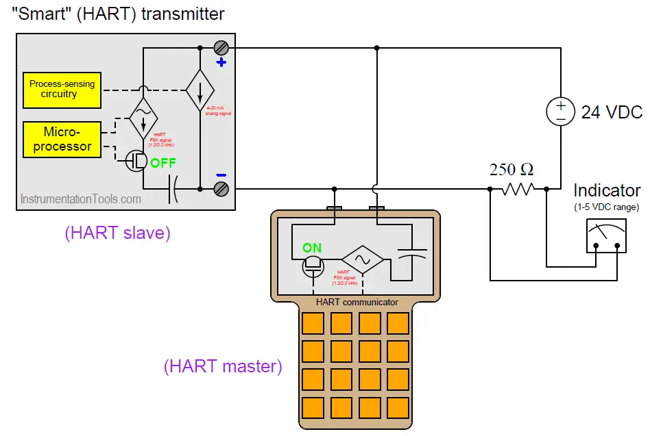
The following schematic diagram shows a simplified HART transmitter connected to a DC loop power supply as well as a HART “communicator” device allowing a human technician to communicate with the transmitter.

The transistor states shown in this diagram reflect the master (“communicator”) device sending data while the slave (smart transmitter) device listens:
Smart HART Transmitter

Since this is a multi-source circuit, with four sources (one AC current source and one DC current source inside the smart transmitter, one AC voltage source in the HART communicator, and one DC voltage source providing loop power), we may apply the Superposition Theorem to determine the combined effect of these sources together in one circuit.

Use the Superposition Theorem to determine the voltage present between the indicator’s terminals, assuming the transmitter happens to be outputting a 50% (12 mA) analog signal, and the HART communicator happens to be outputting a 400 mV AC signal at 2200 Hz at the moment of our analysis.

Solution:

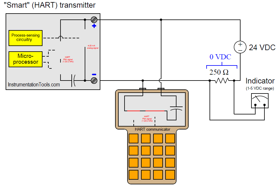
Recall that the Superposition Theorem works by considering one source at a time, with all other sources “disabled” and replaced by their respective internal impedances. With four sources, this means we must analyze the circuit four times over (once for each active source), and then superimpose the results of all four analyses.

Analysis #1: (DC loop power source only)

HART communicator features and connection

Here, we see what the loop power supply does on its own, with all current sources opened (infinite internal impedance) and all other voltage sources shorted (zero internal impedance). The result is an open circuit, with nothing dropped across the 250 ohm resistor.

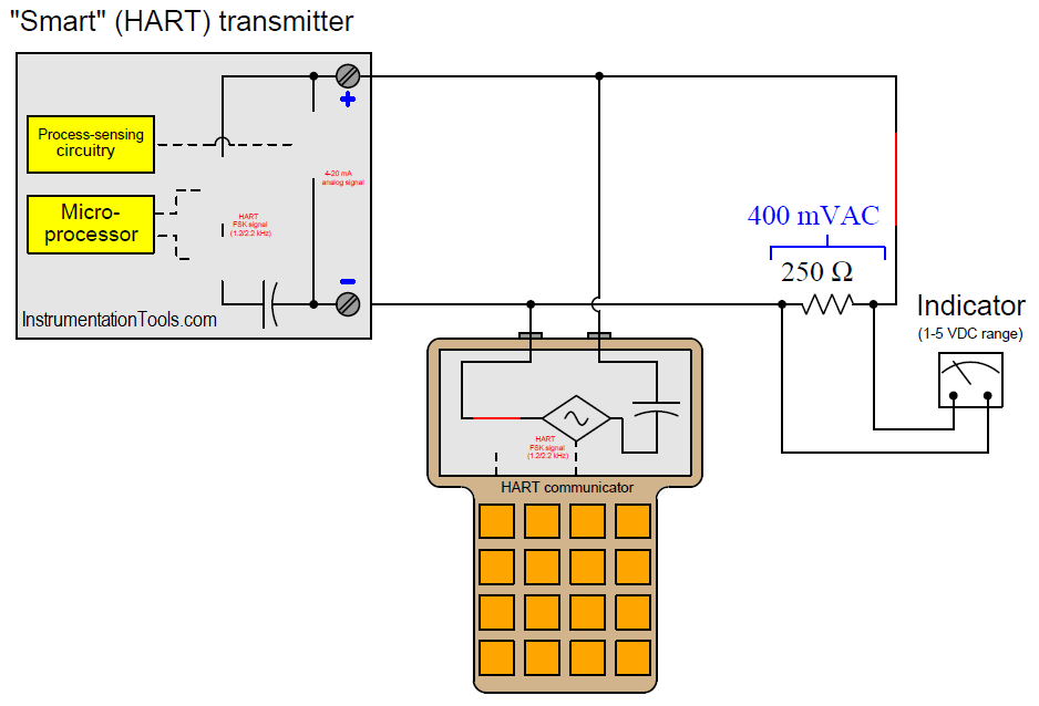
Analysis #2: (HART communicator source only)

HART Communication Systems

Here, we see what the HART communicator’s AC voltage source does on its own, with all current sources opened (infinite internal impedance) and all other voltage sources shorted (zero internal impedance).

The result is the communicator’s AC voltage dropped entirely across the resistor (and also across the terminals of the smart transmitter where the microprocessor will be able to read it). We are assuming that the coupling capacitor’s impedance is negligible.

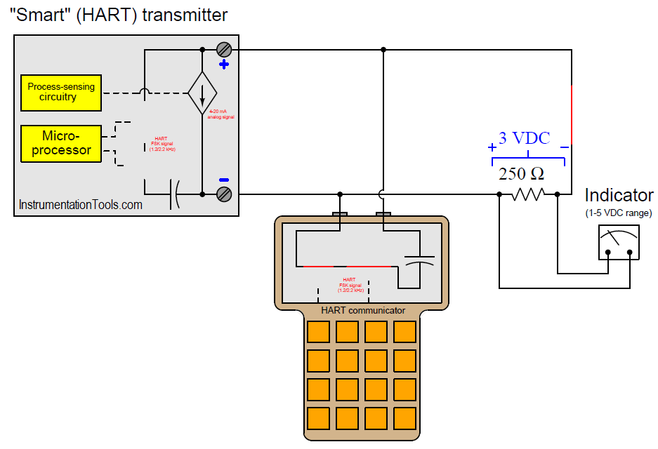
Analysis #3: (transmitter analog source only)

Analysis of HART communicator and Smart HART Transmitter

Here, we see what the smart transmitter’s DC current source does on its own, with all other current sources opened (infinite internal impedance) and all voltage sources shorted (zero internal impedance).

The result is a 3 volt drop across the resistor based on Ohm’s Law (V = IR = 12 mA × 250 = 3 volts).

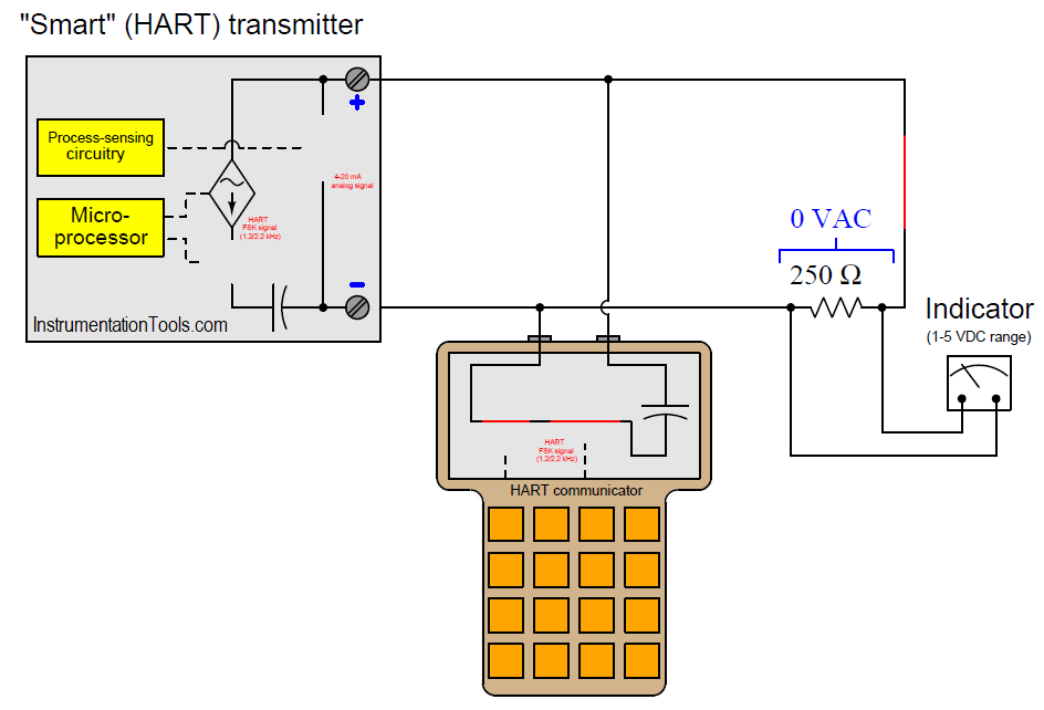
Analysis #4: (transmitter HART source only)

HART Transmitter Communication

Here, we see what the smart transmitter’s AC current source does on its own, with all other current sources opened (infinite internal impedance) and all voltage sources shorted (zero internal impedance). The result is nothing, since the MOSFET in series with this source is turned off.

Superimposing all these results together, we see that the indicator experiences a composite DC+AC signal of 3 volts DC and 400 mV AC at 2200 Hz.

Credits: Tony R. Kuphaldt

Read Next:

  • Calculation using DP Transmitter
  • Fieldbus Flow Transmitter
  • HART Transmitters Loop Check
  • Transmitter NAMUR Signals
  • What is 2-wire Transmitter?
Don't Miss Our Updates
Be the first to get exclusive content straight to your email.
We promise not to spam you. You can unsubscribe at any time.
Invalid email address
You've successfully subscribed !

Continue Reading

Explaining Various Types of Analog Instruments
4-20 mA Loop Splitter
Two out of Three Logic Analogy
Cascade Temperature Control System
Flowmeter Control Strategy
How to Prevent Ground Loops in Analog Circuits?
Share This Article
Facebook Whatsapp Whatsapp LinkedIn Copy Link
Share
Leave a Comment

Leave a Reply Cancel reply

Your email address will not be published. Required fields are marked *

Stay Connected

128.3kFollowersLike
69.1kFollowersFollow
210kSubscribersSubscribe
38kFollowersFollow

Categories

Explore More

What is Instrument Hook Up Diagram ?
Proportional-only Offset
DCS Program to Maintain Draft in Furnace
History of Internet of Things (IOT)
What is a Recorder ?
What is Ratio Control ?
Process Control Fundamentals
Identify Instruments in Piping and instrumentation Diagram

Keep Learning

Single Loop Control

Cascade Control Principle

Functional Safety Terms in Industrial Automation

Functional Safety Terminology in Industrial Automation

Yokogawa DCS Tutorials - Configuration of Analog Input (Transmitter)

Yokogawa DCS Tutorials – Configuration of Analog Input (Transmitter)

Split range control scheme

Overview of Split Range Control

Digital Output Card With Relay and Wet Contact

Wiring Diagrams of PLC and DCS Systems – DI, DO, AI, AO

Layer-2 and Layer-3 Network Switches

Layer-2 and Layer-3 Network Switches

HART Transmitters Loop Checks

Loop Check of 4-20mA or HART Transmitters

What is Instrumentation and Control

What is Instrumentation and Control ?

Learn More

Electromagnetic Fields Objective Questions

Electromagnetic Field Test Questions

Address Resolution Protocol (ARP)

What is the Address Resolution Protocol? – Types of ARP

seven-segment-display-circuit

Seven Segment Display Working Principle

Probe Thermometer

What is a Probe Thermometer? How to Calibrate and Use it?

process chemical analyzer calibration

Automated Calibration

Needle Valve Body Design

What is Needle Valve ?

Laser Doppler anemometer

Laser Doppler Anemometer

Resistor Y and Delta Network Calculation

Y and Delta Resistor Network Calculations

Menu

  • About
  • Privacy Policy
  • Copyright

Quick Links

  • Learn PLC
  • Helping Hand
  • Part Time Job

YouTube Subscribe

Follow US
All rights reserved. Reproduction in whole or in part without written permission is prohibited.
Welcome Back!

Sign in to your account

Username or Email Address
Password

Lost your password?