Inst ToolsInst ToolsInst Tools
  • Courses
  • Automation
    • PLC
    • Control System
    • Safety System
    • Communication
    • Fire & Gas System
  • Instrumentation
    • Design
    • Pressure
    • Temperature
    • Flow
    • Level
    • Vibration
    • Analyzer
    • Control Valve
    • Switch
    • Calibration
    • Erection & Commissioning
  • Interview
    • Instrumentation
    • Electrical
    • Electronics
    • Practical
  • Q&A
    • Instrumentation
    • Control System
    • Electrical
    • Electronics
    • Analog Electronics
    • Digital Electronics
    • Power Electronics
    • Microprocessor
  • Request
Search
  • Books
  • Software
  • Projects
  • Process
  • Tools
  • Basics
  • Formula
  • Power Plant
  • Root Cause Analysis
  • Electrical Basics
  • Animation
  • Standards
  • 4-20 mA Course
  • Siemens PLC Course
Reading: What is Siemens TDC? – Siemens Control System
Share
Notification Show More
Font ResizerAa
Inst ToolsInst Tools
Font ResizerAa
  • Courses
  • Design
  • PLC
  • Interview
  • Control System
Search
  • Courses
  • Automation
    • PLC
    • Control System
    • Safety System
    • Communication
    • Fire & Gas System
  • Instrumentation
    • Design
    • Pressure
    • Temperature
    • Flow
    • Level
    • Vibration
    • Analyzer
    • Control Valve
    • Switch
    • Calibration
    • Erection & Commissioning
  • Interview
    • Instrumentation
    • Electrical
    • Electronics
    • Practical
  • Q&A
    • Instrumentation
    • Control System
    • Electrical
    • Electronics
    • Analog Electronics
    • Digital Electronics
    • Power Electronics
    • Microprocessor
  • Request
Follow US
All rights reserved. Reproduction in whole or in part without written permission is prohibited.
Inst Tools > Blog > PLC Tutorials > What is Siemens TDC? – Siemens Control System

What is Siemens TDC? – Siemens Control System

TDC is a product of Siemens Automation and stands for Technology And Drives Control. Learn what is Simatic TDC.

Last updated: March 4, 2024 11:51 am
Editorial Staff
PLC Tutorials
No Comments
Share
5 Min Read
SHARE

In industrial automation, there are many new technologies for making a system work more efficiently and accurately. Apart from a PLC, there are other types of controllers available for proper operation. One such device is TDC.

TDC is a product of Siemens Automation and stands for Technology And Drives Control. There are very few devices in industrial automation that stand out in competition with it, due to its unique working.

TDC is used mostly in large-scale and critical applications requiring uniformity, efficiency, synchronization, and accuracy. In this post, we will see the concept of Simatic TDC.

Siemens TDC

What is Siemens TDC - Siemens Control System

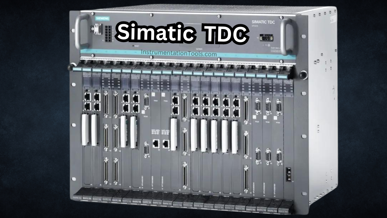
Siemens has a product as discussed earlier, called Simatic TDC (Siemens TDC). It is an automation system that comprises multiple processors mounted on a single rack. This processor can be said to be a PLC for simple understanding.

This means that it is modular in design. Modular PLC systems are ones where IOs can be expanded by either connecting through communication or by connecting to expansion slots of the CPU physically.

Apart from multiple PLCs thus, extra IOs can also be connected through modules. The rack is one where all the processors are mounted, and due to this common backplane architecture, data transfer happens quickly. It behaves as if the main CPU takes data from digital or analog IO modules in a normal single CPU connection, where you get the IO values instantly.

This architecture makes the product useful for machine automation applications, where synchronization and accuracy are a must. Also, as the name implies, it works specifically for connecting multiple VFDs and processing them quickly to talk with each other as smoothly as possible.

Refer to the below image. The TDC architecture consists of a rack, a processor of multiple quantities (each processor having Profinet connectivity), an optional communication module having Profibus DP connectivity, and DI and DO modules.

Siemens TDC Architecture

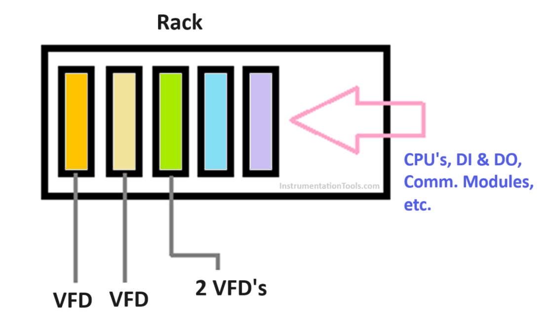
Each processor will be connected to either a single VFD or multiple VFDs, depending on the ports of each processor consumed. There are libraries inside the engineering software, that allow direct communication between each processor. This reduces the need for any extra programming to be done for communication.

Suppose there are 6 VFDs in the system for 4 processors. It is required that the second VFD be started after the first one and so on. This means they will be all interdependent. When any of the VFDs fails, the feedback must be passed to all the other VFDs; which will stop the process in sequence.

This task is done by the TDC, which will continuously synchronize data between all the VFDs. If multiple PLCs were used in this case, then communication between them would introduce some lagging time and this would affect the process in the long run or under emergency situations.

So, TDC makes tasks easier by using in-built libraries and allowing direct and swift communication between them. Each controller just needs to be programmed with the configuration and it will then automatically run in synchronization with other PLCs.

Looking at all this, we get to know that TDC is a closed-loop system. It works on feedback and this helps to run the VFDs in tandem with each other, with less amount of programming to be done.

Also, you get enormous status information due to the common rack system, which helps in easy diagnostics and troubleshooting of the system. The scan time is very less in this system which makes it faster for operation (can go up to 100 microseconds).

You can configure up to 20 processors per rack in this system. Likewise, a total of 44 such racks can be communicated and synchronized with each other. So, you can imagine how vast a system can be designed for complex machine automation controls.

If you liked this article, then please subscribe to our YouTube Channel for Instrumentation, Electrical, PLC, and SCADA video tutorials.

You can also follow us on Facebook and Twitter to receive daily updates.

Read Next:

  • Free Schneider PLC Training
  • Real-time PLC Automation Projects
  • How to Choose a PLC for a Project?
  • How to Configure Distributed IO?
  • Siemens Tia Portal Free PLC Course
Don't Miss Our Updates
Be the first to get exclusive content straight to your email.
We promise not to spam you. You can unsubscribe at any time.
Invalid email address
You've successfully subscribed !

Continue Reading

Testing and Validation in PLC Development
PLC Programmer Salary and Future Career Scope
What is a Annunciator Panel?
All About Fieldbus Protocols
Step-by-Step Guide to Choose Right Fuse for a Panel
D Flip Flop PLC Ladder Logic
Share This Article
Facebook Whatsapp Whatsapp LinkedIn Copy Link
Share
Leave a Comment

Leave a Reply Cancel reply

Your email address will not be published. Required fields are marked *

Stay Connected

128.3kFollowersLike
69.1kFollowersFollow
210kSubscribersSubscribe
38kFollowersFollow

Categories

Explore More

Actuator Sensor Interface (ASi) Protocol in PLC
PLC Automatic Door Control System – Programming Example
Difference Between FC and FB in Tia Portal
What are High-Speed Inputs in PLC?
Converter Instruction in Siemens PLC Programming
Set the S5 Timer Value by a Memory Word
Timer-Based Sequential PLC Program with One Button
How Does Redundant Power Supply Work?

Keep Learning

Online time of the PLC

System and Local Time in PLC

Simple PLC example Hardware configurations

Muting Functions of Safety Control Circuits – PLC Example

PLC SCADA Water Pump

PLC Program for Controlling a Water Pump with 3 Power Sources

Types of Scan Time in a PLC

#16 PLC Best Practices – Create Trend for Cycle Time on HMI

PLC engineering software

How to Download GX Works? Mitsubishi PLC Software

Siemens OB Blocks

Siemens PLC Organization Blocks (OB)

Industrial Networking Interview Questions

Industrial Networking and Wireless Interview Questions

PLC Program for Filling Operation

PLC Program for Continuous Filling Operation

Learn More

Manual Call Point Testing Procedure

Manual Call Point Testing Procedure

PLC Question Bank

PLC Question Bank

Thermovcouple Circuit

Thermocouple and its Principle

Namur Digital Input Card

What is Namur Digital Input Card?

Unbalanced Bridge Circuit

Bridge Circuit Construction

Limit Switch Installation

What is a Limit Switch ?

Pressure Transmitter Working Principle

Gage and Absolute Pressure Transmitters Principle

Power Electronics Projects

Top 100 Power Electronics Projects for Engineering Students

Menu

  • About
  • Privacy Policy
  • Copyright

Quick Links

  • Learn PLC
  • Helping Hand
  • Part Time Job

YouTube Subscribe

Follow US
All rights reserved. Reproduction in whole or in part without written permission is prohibited.
Welcome Back!

Sign in to your account

Username or Email Address
Password

Lost your password?