This is Program for Siemens PLC Mathematics Instructions.
Implement ADD, SUB, MUL, DIV, MOD and NEG instructions in S7-1200 PLC using ladder diagram language.
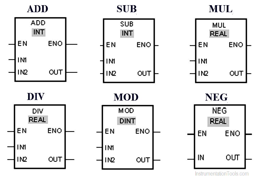
We can use the Add instruction to add the value at input IN1 and the value at input IN2 and query the sum at output OUT (OUT := IN1+IN2).
Subtract instruction is used to subtract the value at input IN2 from the value at input IN1 and query the difference at output OUT (OUT := IN1-IN2).
Multiply instruction is used to multiply the value at input IN1 with the value at input IN2 and query the product at output OUT (OUT := IN1*IN2).
Divide instruction is used to divide the value at input IN1 by the value at input IN2 and query the quotient at output OUT (OUT := IN1/IN2).
We can use the Return remainder of division instruction to divide the value at input IN1 by the value at input IN2 and query the remainder of division at output OUT.
We can use the “Create twos complement” instruction to change the sign of the value at the IN input and query the result at the OUT output. If there is a positive value at input IN, for example, the negative equivalent of this value is sent to output OUT.
In this program we have used Siemens S7-1200 PLC and TIA Portal Software for programming.
The value of MW0 is added to the value of MW2.The result of the addition is stored in the MW4.
The value of MW6 is subtracted from the value of MW8.The result of the subtraction is stored in MW10.
The value of operand MW12 is multiplied by the value of MW14. The result of the multiplication is stored in MW16.
The value of operand MW18 is divided by the value of MW20. The division result is stored in MW22.
The value of MD100 is divided by the value of MD104. The remainder of division is stored in operand MD108.
The sign of the value at input MW24 is changed and the result is provided at output MW26.
If you liked this article, then please subscribe to our YouTube Channel for PLC and SCADA video tutorials.
You can also follow us on Facebook and Twitter to receive daily updates.
Read Next:
Rotating equipment packages such as pumps, compressors, turbines need the lube oil consoles for their…
This article explains how to blink lights in ladder logic with a detailed explanation video…
In this article, a simple example will teach you the conversion from Boolean algebra to…
In this article, you will learn the PLC cooking timer example for kitchen automation using…
Learn an example PLC program to control a pump based on level sensors using ladder…
In the PLC timer application for security camera recording, when motion is detected then camera…


