Inst ToolsInst ToolsInst Tools
  • Courses
  • Automation
    • PLC
    • Control System
    • Safety System
    • Communication
    • Fire & Gas System
  • Instrumentation
    • Design
    • Pressure
    • Temperature
    • Flow
    • Level
    • Vibration
    • Analyzer
    • Control Valve
    • Switch
    • Calibration
    • Erection & Commissioning
  • Interview
    • Instrumentation
    • Electrical
    • Electronics
    • Practical
  • Q&A
    • Instrumentation
    • Control System
    • Electrical
    • Electronics
    • Analog Electronics
    • Digital Electronics
    • Power Electronics
    • Microprocessor
  • Request
Search
  • Books
  • Software
  • Projects
  • Process
  • Tools
  • Basics
  • Formula
  • Power Plant
  • Root Cause Analysis
  • Electrical Basics
  • Animation
  • Standards
  • 4-20 mA Course
  • Siemens PLC Course
Reading: Series Circuit
Share
Font ResizerAa
Inst ToolsInst Tools
Font ResizerAa
  • Courses
  • Design
  • PLC
  • Interview
  • Control System
Search
  • Courses
  • Automation
    • PLC
    • Control System
    • Safety System
    • Communication
    • Fire & Gas System
  • Instrumentation
    • Design
    • Pressure
    • Temperature
    • Flow
    • Level
    • Vibration
    • Analyzer
    • Control Valve
    • Switch
    • Calibration
    • Erection & Commissioning
  • Interview
    • Instrumentation
    • Electrical
    • Electronics
    • Practical
  • Q&A
    • Instrumentation
    • Control System
    • Electrical
    • Electronics
    • Analog Electronics
    • Digital Electronics
    • Power Electronics
    • Microprocessor
  • Request
Follow US
All rights reserved. Reproduction in whole or in part without written permission is prohibited.
Inst Tools > Blog > Electrical Theory > Series Circuit

Series Circuit

Last updated: July 23, 2018 10:47 am
Editorial Staff
Electrical Theory
No Comments
Share
0 Min Read
SHARE

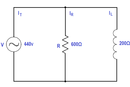
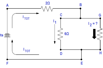
A series circuit is a circuit where there is only one path for current flow.

In a series circuit (Figure 16), the current will be the same throughout the circuit. This means that the current flow through R1 is the same as the current flow through R2 and R3.

Series Circuit

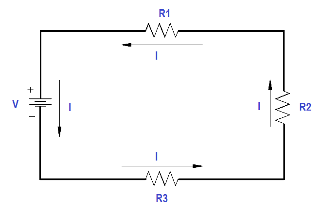
Figure 16 Series Circuit

Don't Miss Our Updates
Be the first to get exclusive content straight to your email.
We promise not to spam you. You can unsubscribe at any time.
Invalid email address
You've successfully subscribed !

Continue Reading

AC Generation Analysis : Effective Values, Phase Angle and Frequency
Generator Action in a Motor
Transformer Voltage Ratio
Three Phase Wattmeter
Inductance and Inductive Reactance
Types of AC Generators
Share This Article
Facebook Whatsapp Whatsapp LinkedIn Copy Link
Share
Leave a Comment

Leave a Reply Cancel reply

Your email address will not be published. Required fields are marked *

Stay Connected

128.3kFollowersLike
69.1kFollowersFollow
210kSubscribersSubscribe
38kFollowersFollow

Categories

Explore More

Resonance, Resonant Frequency, Series and Parallel Resonance
Motor Controllers
Parallel Circuit
Thermocouples
Reading Electrical Schematics
Low Voltage Air Circuit Breaker Principle
Schematic Diagram
Induction Motor Torque Versus Slip

Keep Learning

Calculate Power in Parallel RL Circuit

Calculate Power in Parallel RL Circuit

Auto Transformer Schematic

Classification of Transformers

AC Generator Nameplate Ratings

AC Generator Nameplate Ratings

relationship between resistance, reactance, and impedance

Impedance

Current Law

Applying Kirchhoff’s Current Law

circuit breaker principle

What is a circuit breaker ?

Shorted Parallel Circuit

Parallel Short Circuit Faults

Half-Wave Rectifier Circuit

Half-Wave Rectifier Circuit

Learn More

Pressure Transmitters Installation Factors

Pressure Transmitters Installation Tips

Difference Between Single-stage and Multi-stage Compressor

Difference Between Single-stage and Multi-stage Compressor

Which instrument is faulty

Which Instrument is Faulty? Transmitter, Recorder, or Controller

CO2 Stripper Old Differential Pressure Transmitter Stopped Working

CO2 Stripper Old Differential Pressure Transmitter Stopped Working

How to Setup a Smart Transmitter Using a HART Communicator

How to Configure a Smart Transmitter Using a HART Communicator?

PLC Cabinet

PLC Programming Videos

Level Transmitter Design

Level Transmitter and Level Gauge Design Tips

Power Electronics Objective Questions

Cycloconverters Objective Questions

Menu

  • About
  • Privacy Policy
  • Copyright

Quick Links

  • Learn PLC
  • Helping Hand
  • Part Time Job

YouTube Subscribe

Follow US
All rights reserved. Reproduction in whole or in part without written permission is prohibited.
Welcome Back!

Sign in to your account

Username or Email Address
Password

Lost your password?