PLC is a very important part of industrial automation. It is the base of automation and every PLC programmer or automation engineer must design it properly so that it works properly. It is not just about programming, but ultimately how you design the PLC system.
Safety Considerations in PLC System Design
We all think that if write a program properly with all the interlocks, sequence, and flow properly, then our PLC system is ready to use. But, it must be noted that one of the most important parameters in designing any system is safety. So, similarly, a PLC system must be designed considering safety in mind. In this article, we will learn the safety considerations when designing a PLC system.
Power Supply
This is the first and foremost parameter in considering PLC design. There are two types of power supplies in the panel – DC and AC. DC is usually 12-24V DC and AC is usually 110V AC or 230V AC.
PLC is powered up by either of the supplies and the field instruments too are powered up by either of the supplies. If a panel has a single SMPS or 230V single bus bar, then it becomes easy for designers to wire the system. If a panel has multiple power supplies, then there are chances that you will connect a positive wire from one supply and a negative wire from another supply by mistake. This will instead complex your system and make troubleshooting harder. So, a single power supply also minimizes line interference and prevents faulty input signals coming from a stable AC source to the power supply and CPU.
Multiple power supplies are unwanted and also create more chances of short circuits and frequent breakdowns. So, power supply design is a very important factor for safely operating the PLC system.
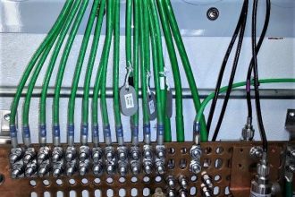
Earthing
Earthing, as we all know, is required to pass any leakage current to the ground. This prevents electric shock, noise, and electromagnetic interference. The standard neutral to earthing voltage must be less than 0.5V in industrial areas.
A slightly higher side of 1V is acceptable, but if it is above that, then it means the earthing is not proper and leakage happening in electrical signals will hamper the performance. PLC power supply, and IO channels, must be properly grounded and connected to the earth bus bar in the panel.
Also, instrument earthing and power earthing must be separate; otherwise, any merge in the earthing will create short circuits or interference in signals.
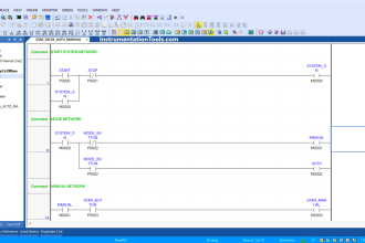
Critical Digital Input Signals
Every PLC system must have critical inputs like emergency stop, panel power failure, and air pressure. Also, all these signals must be connected in NC (normally closed) format.
The emergency stop is used to stop the system suddenly when an operator presses this button, panel power failure is used to stop the system when there is any problem in the phase power supply, and the air pressure signal denotes whether air is required to operate valves or other pneumatic outputs is proper or not.
All actions should stop immediately if any of these inputs fail. In some large systems, it is also observed that if the emergency is pressed, then instead of stopping the whole system, provide an emergency stop for individual large rating outputs. Due to this, the operator can isolate every system easily and operate other systems instead of stopping the whole system.
Manual Mode Interlocks
Programmers always take manual mode logic lightly. Just turning on or off the outputs is their motive. However, it must be noted that any irregular operation of outputs manually can hamper the system’s performance. If the system is very critical, then it can cause life-threatening issues to the personnel nearby.
So, it is recommended to apply alarms or other critical interlocks in manual mode too. This prevents the operator from operating the system randomly. Also, the safety of the PLC system is ensured due to this logic.
Alarms
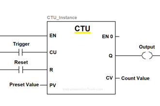
All alarms given in a control logic document are usually taken by the programmers in the program. However, PLC programmers must provide some additional safety alarms in the system, according to IO’s taken in the PLC.
These are usually run feedback alarms, trip feedback alarms, over or under travel alarms, sensor failure alarms, PLC channel failure alarms, thermal overload alarms, thermostat alarms, over or under voltage alarms, etc. These alarms vary from system to system, based on the actual inputs taken.
But, if any of these inputs are not there, then it is recommended that programmers suggest the same to customers for considering them. This prevents the system from operating in a malfunctioning way.
In this way, we saw some general safety considerations when designing a PLC system.
If you liked this article, then please subscribe to our YouTube Channel for Instrumentation, Electrical, PLC, and SCADA video tutorials.
You can also follow us on Facebook and Twitter to receive daily updates.
Read Next:
- Motor Faceplate in Graphics
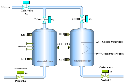
- HMI and VFD Control System
- Update PLC Firmware Version
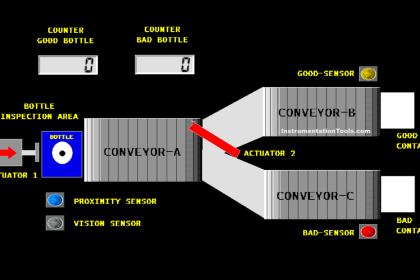
- PLC Sorting Machine System
- PID Controller Control System