By using this site, you agree to the Privacy Policy and Terms of Use.
Accept
Inst ToolsInst ToolsInst Tools
  • Ask
  • Courses
  • Videos
  • Q & A
    • Interview
      • Instrumentation
      • Electronics
      • Electrical
      • Practical Questions
    • MCQ
      • Instrumentation MCQ
      • Electrical MCQ
      • Electronics MCQ
      • Control Systems MCQ
      • Analog Electronics MCQ
      • Digital Electronics MCQ
      • Power Electronics MCQ
      • Microprocessor MCQ
      • Multiple Choice Questions
  • EE
    • Electronics
      • Electronics Q & A
      • Electronic Basics
      • Electronic Devices & Circuits
      • Electronics Animation
      • Digital Electronics
    • Electrical
      • Electrical Basics
      • Electrical Q & A
      • Power Electronics
      • Electrical Machines
      • Electrical Animation
      • Power Systems
      • Switchgear & Protection
      • Transmission & Distribution
  • Measure
    • Control Valves
    • Calibration
    • Temperature
    • Pressure
    • Flow
    • Level
    • Analyzers
    • Switches
    • Vibration
    • Solenoid Valve
  • Control
    • PLC Tutorials
    • Control Systems
    • Safety Instrumented System (SIS)
    • Communication
    • Fire & Gas System
  • More
    • Design
    • Tools
    • Animation
    • Basics
    • Formulas
    • Standards
    • TextBooks
    • Common
    • Software
    • Excel Tools
    • Erection & Commissioning
    • Process Fundamentals
    • Videos
    • Books
Search
All rights reserved. Reproduction in whole or in part without written permission is prohibited.
Reading: RTD Wheatstone Bridge Circuits
Share
Notification Show More
Font ResizerAa
Inst ToolsInst Tools
Font ResizerAa
  • Ask
  • Courses
  • Videos
  • Q & A
  • EE
  • Measure
  • Control
  • More
Search
  • Ask
  • Courses
  • Videos
  • Q & A
    • Interview
    • MCQ
  • EE
    • Electronics
    • Electrical
  • Measure
    • Control Valves
    • Calibration
    • Temperature
    • Pressure
    • Flow
    • Level
    • Analyzers
    • Switches
    • Vibration
    • Solenoid Valve
  • Control
    • PLC Tutorials
    • Control Systems
    • Safety Instrumented System (SIS)
    • Communication
    • Fire & Gas System
  • More
    • Design
    • Tools
    • Animation
    • Basics
    • Formulas
    • Standards
    • TextBooks
    • Common
    • Software
    • Excel Tools
    • Erection & Commissioning
    • Process Fundamentals
    • Videos
    • Books
Follow US
All rights reserved. Reproduction in whole or in part without written permission is prohibited.
Inst Tools > Blog > Temperature Measurement > RTD Wheatstone Bridge Circuits
Temperature Measurement

RTD Wheatstone Bridge Circuits

Last updated: February 9, 2018 5:06 am
Editorial Staff
Share
5 Min Read
SHARE

Every type of metal has a unique composition and has a different resistance to the flow of electrical current. This is termed the resistively constant for that metal. For most metals the change in electrical resistance is directly proportional to its change in temperature and is linear over a range of temperatures. This constant factor called the temperature coefficient of electrical resistance (short formed TCR) is the basis of resistance temperature detectors. The RTD can actually be regarded as a high precision wire wound resistor whose resistance varies with temperature. By measuring the resistance of the metal, its temperature can be determined.

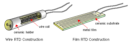
Several different pure metals (such as platinum, nickel and copper) can be used in the manufacture of an RTD. A typical RTD probe contains a coil of very fine metal wire, allowing for a large resistance change without a great space requirement. Usually, platinum RTDs are used as process temperature monitors because of their accuracy and linearity.

To detect the small variations of resistance of the RTD, a temperature transmitter in the form of a Wheatstone bridge is generally used. The circuit compares the RTD value with three known and highly accurate resistors.

Two Wire RTD Wheatstone bridge Circuit

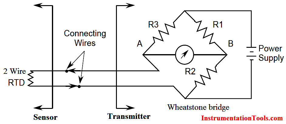
A Wheatstone bridge consisting of an RTD, three resistors, a voltmeter and a voltage source is illustrated in Above Figure. In this circuit, when the current flow in the meter is zero (the voltage at point A equals the voltage at point B) the bridge is said to be in null balance. This would be the zero or set point on the RTD temperature output. As the RTD temperature increases, the voltage read by the voltmeter increases. If a voltage transducer replaces the voltmeter, a 4-20 mA signal, which is proportional to the temperature range being monitored, can be generated.

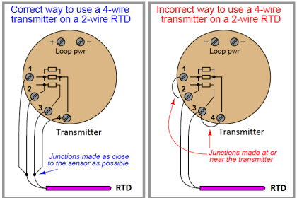
As in the case of a thermocouple, a problem arises when the RTD is installed some distance away from the transmitter. Since the connecting wires are long, resistance of the wires changes as ambient temperature fluctuates. The variations in wire resistance would introduce an error in the transmitter. To eliminate this problem, a three-wire RTD is used.

Three Wire RTD Wheatstone bridge Circuit

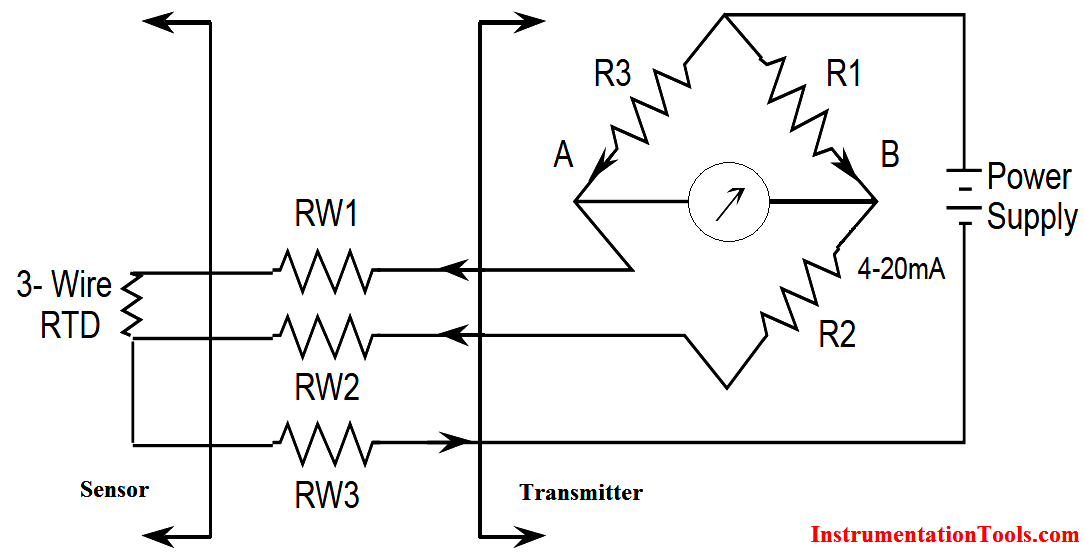
The connecting wires (w1, w2, w3) are made the same length and therefore the same resistance. The power supply is connected to one end of the RTD and the top of the Wheatstone bridge. It can be seen that the resistance of the right leg of the Wheatstone bridge is R1 + R2 + RW2. The resistance of the left leg of the bridge is R3 + RW3 + RTD. Since RW1 = RW2, the result is that the resistances of the wires cancel and therefore the effect of the connecting wires is eliminated.

RTD Advantages and Disadvantages

Advantages:

  • The response time compared to thermocouples is very fast – in the order of fractions of a second.
  • An RTD will not experience drift problems because it is not selfpowered.
  • Within its range it is more accurate and has higher sensitivity than a thermocouple.
  • In an installation where long leads are required, the RTD does not require special extension cable.
  • Unlike thermocouples, radioactive radiation (beta, gamma and neutrons) has minimal effect on RTDs since the parameter measured is resistance, not voltage.

Disadvantages:

  • Because the metal used for a RTD must be in its purest form, they are much more expensive than thermocouples.
  • In general, an RTD is not capable of measuring as wide a temperature range as a thermocouple.
  • A power supply failure can cause erroneous readings
  • Small changes in resistance are being measured, thus all connections must be tight and free of corrosion, which will create errors.

Failure Modes:

  • An open circuit in the RTD or in the wiring between the RTD and the bridge will cause a high temperature reading.
  • Loss of power or a short within the RTD will cause a low temperature reading.
Don't Miss Our Updates
Be the first to get exclusive content straight to your email.
We promise not to spam you. You can unsubscribe at any time.
Invalid email address
You've successfully subscribed !
Thermocouple Temperature Measurement Errors
Thermocouple Cold Junction Compensation
Helix Bimetallic Thermometer Principle
Testing a Thermocouple With a Multimeter
Thermowell Installation near Critical Equipment
Share This Article
Facebook Whatsapp Whatsapp LinkedIn Copy Link
Share
3 Comments
  • Sabir Malik. says:
    August 8, 2016 at 1:48 pm

    Such a good site to increase knowledge and development.
    Thanks all.

    Reply
  • Ps says:
    September 17, 2017 at 6:14 am

    Thank you so much to put up all this important info on this site really helps alot.

    Reply
  • NathanW says:
    May 2, 2022 at 1:06 am

    Great explanation of 2-wire and 3-wire lead systems. Thank you.

    Reply

Leave a Reply Cancel reply

Your email address will not be published. Required fields are marked *

Stay Connected

128.3kFollowersLike
69.1kFollowersFollow
206kSubscribersSubscribe
38kFollowersFollow

Latest

Top Non-PLC Certification Courses for Automation Professionals
Common
Things You Need to Know About DeviceNet
Communication
Why is IEC 60269 Important
Why is IEC 60269 Important? – Electrical Applications
Standards
NAMUR OPEN ARCHITECTURE
What is NAMUR OPEN ARCHITECTURE?
Control Systems

More Articles

Flow Measurement

Continuous Flow Measurement

PLC Best Practices

#1 PLC Best Practices – Split PLC Code into Modules

How to test SCR using Multimeter

How to test SCR using Multimeter

Valve Technician Interview Questions

Valve Technician Interview Questions

Phase Watcher Multiphase Flow Meter (MPFM) Procedure

Functional Block Diagram of XNOR Logic Gate

PLC Functional Block Diagram for Logic Gates

Stop Check valve

What is Stop Check valve ?

Component De-rating

Component De-rating in Control Systems

//

Inst Tools

Sign Up for Our Newsletter

Subscribe to our newsletter to get our newest articles instantly!

[mc4wp_form id=”847″]

Follow US
All rights reserved. Reproduction in whole or in part without written permission is prohibited.
Welcome Back!

Sign in to your account

Username or Email Address
Password

Lost your password?