In this article, you will learn the Response Time test of RTD and thermocouple.
The Process Parameters in the Industry or Power Plant must be continuously Monitored and Controlled.
The Temperature is one of the most important parameters that need to be controlled. RTD and Thermocouples are used to measure the Temperature.
The Response Time of Temperature Element is tested in all Power Plants and other industries.
Methods of Response Time Test of Temperature Element are:
Generally, the Response Time of the Temperature Element has been characterized by a single parameter called Plunge Time (T).
It is the time taken by the Temperature Element to produce an output of 65% to 66% of its actual Range value, even after the step change in temperature.
It is defined as the ratio of change in Resistance to the Electric Power generated in RTD’s Sensing Element.
It applies only to RTDs and is performed to detect the gross change in the Response Time of RTDs.
The Self-Heating Index is performed using Wheatstone’s bridge Circuit.
The unit is expressed in ohms/watt.
The Procedure for Self-Heating Index for RTD is as follows
This method was developed to measure the Response Time of RTD and Thermocouple remotely when the sensor is installed in the Process Field.
The Loop Current Step Response (LCSR) Test Procedure differs for RTDs and Thermocouples
The Loop Current Step Response (LCSR) Test Procedure for RTD:
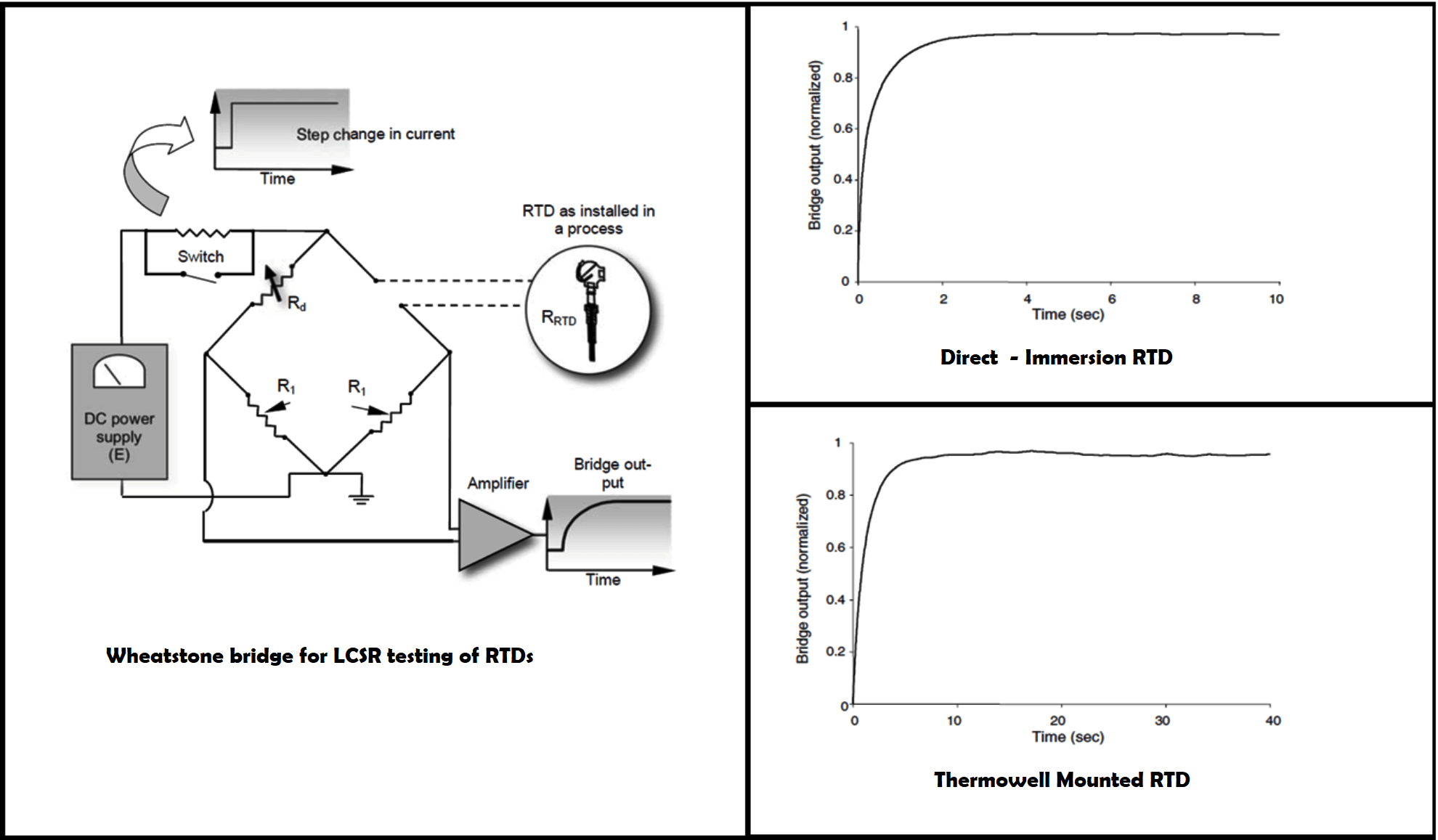
The above diagram shows the graph of 2 LCSR test transients:
But these transients are from the LCSR testing of the RTDs in power plants using a heating current of about 40 mA.
The Direct-Immersion RTD has a faster Response Time that heats up faster than the Thermowell-mounted RTD.
And these transients are caused by internal heating and cannot provide the RTD’s response time until after the data is transformed.
To provide the necessary current for the LCSR test, the Power Supply in the Wheatstone bridge is adjusted so the high current must lie between 30 and 50 mA, depending on the RTD and the process in which it is installed.
If the RTD is in a stable process, then only 30 mA is enough. On the other hand, if the RTD is in a process that has large temperature fluctuations, a higher current of 50 mA is required to improve the Signal to Noise (S/N) ratio.
To adjust the amplitude of the LCSR signal an amplifier can be used at the output of the Wheatstone bridge.
The Wheatstone bridge’s output voltage (V) changes almost linearly with changes in RTD resistance (δR) during the LCSR test.
The LCSR test procedure for Thermocouple and RTD is different although the principle of the test and data analysis is the same for Both RTD and Thermocouple.
For LCSR testing of thermocouples, to heat the sensor an AC signal is required instead of a DC signal. This is because AC cancels the Peltier effect at the thermocouple junction.
The Higher current of 500mA is also required because the thermocouples circuit resistance is distributed along the length of the Thermocouple. And the whole Thermocouple unit is heated on applying the LCSR test current
Peltier effect: It is defined as the change in heat content when 1 coulomb of charge crosses the junction. If current flows in the same direction heat are liberated in the hot junction and heat is absorbed in the cold junction. And if the current flows in the opposite direction heat are liberated in the cold junction and heat is absorbed in the hot junction.
The difference between the LCSR testing of RTD and Thermocouple is that
In LCSR testing of RTDs, the data is collected as current is running through the circuit and the RTD is heating up.
In LCSR testing of Thermocouples, the data is collected after the current is switched off and while the thermocouple is cooling down to the ambient temperature
To obtain the Thermocouple response time, the LCSR transient must be analyzed using the same procedure as RTDs. Therefore, the LCSR cooling transient for thermocouples is often inverted when presenting the plot of the raw data.
Reference: Maintenance of Process Instrumentation in Power Plants H.M. Hashemian
In this article, you will learn the PLC cooking timer example for kitchen automation using…
Learn an example PLC program to control a pump based on level sensors using ladder…
In the PLC timer application for security camera recording, when motion is detected then camera…
In this example, we will learn batch mixing with PLC ladder logic program using timer…
This PLC example on manufacturing line assembly is an intermediate-level PLC program prepared for the…
In this article, you will learn the PLC programming example with pushbutton and motor control…


