Inst ToolsInst ToolsInst Tools
  • Courses
  • Automation
    • PLC
    • Control System
    • Safety System
    • Communication
    • Fire & Gas System
  • Instrumentation
    • Design
    • Pressure
    • Temperature
    • Flow
    • Level
    • Vibration
    • Analyzer
    • Control Valve
    • Switch
    • Calibration
    • Erection & Commissioning
  • Interview
    • Instrumentation
    • Electrical
    • Electronics
    • Practical
  • Q&A
    • Instrumentation
    • Control System
    • Electrical
    • Electronics
    • Analog Electronics
    • Digital Electronics
    • Power Electronics
    • Microprocessor
  • Request
Search
  • Books
  • Software
  • Projects
  • Process
  • Tools
  • Basics
  • Formula
  • Power Plant
  • Root Cause Analysis
  • Electrical Basics
  • Animation
  • Standards
  • 4-20 mA Course
  • Siemens PLC Course
Reading: PLC Pump Permissive Interlocks
Share
Font ResizerAa
Inst ToolsInst Tools
Font ResizerAa
  • Courses
  • Design
  • PLC
  • Interview
  • Control System
Search
  • Courses
  • Automation
    • PLC
    • Control System
    • Safety System
    • Communication
    • Fire & Gas System
  • Instrumentation
    • Design
    • Pressure
    • Temperature
    • Flow
    • Level
    • Vibration
    • Analyzer
    • Control Valve
    • Switch
    • Calibration
    • Erection & Commissioning
  • Interview
    • Instrumentation
    • Electrical
    • Electronics
    • Practical
  • Q&A
    • Instrumentation
    • Control System
    • Electrical
    • Electronics
    • Analog Electronics
    • Digital Electronics
    • Power Electronics
    • Microprocessor
  • Request
Follow US
All rights reserved. Reproduction in whole or in part without written permission is prohibited.
Inst Tools > Blog > PLC Tutorials > PLC Pump Permissive Interlocks

PLC Pump Permissive Interlocks

Last updated: March 4, 2021 4:41 pm
Editorial Staff
PLC Tutorials Practical Questions
5 Comments
Share
5 Min Read
SHARE

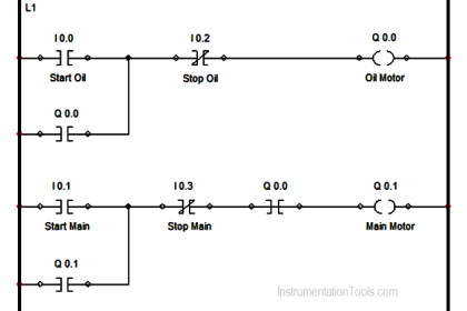
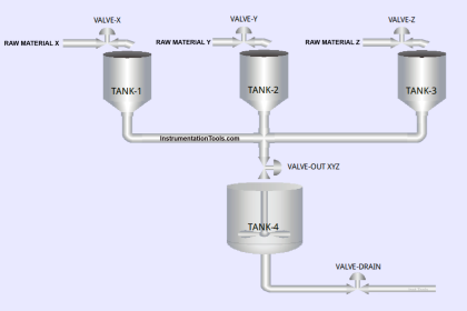
The following PLC program was written to control the operation of a large electric motor-driven pump.

Contents
PLC Pump Permissive InterlocksAnswer :“Valve open” limit switch:Low oil pressure:High bearing temperature:

A variety of “permissive” inputs protect the pump from damage under abnormal conditions, and one permissive in particular (“valve open”) will only allow the pump to start up if one of the valves in the piping system is in the full-open position:

PLC Pump Permissive Interlocks

PLC Pump Permissive Interlocks

Identify the type of contact (either NO or NC) necessary for each of these electrical switch contacts, based on the trip condition (either high or low) and how each input is applied in the PLC program:

  1. Start pushbutton = NO or NC?
  2. Throttling valve open limit = NO or NC?
  3. Stop pushbutton = NO or NC?
  4. High bearing temperature = NO or NC?
  5. High vibration = NO or NC?
  6. High motor temperature = NO or NC?
  7. Low oil pressure = NO or NC?

Answer :

  1. Start pushbutton = NO
  2. Throttling valve open limit = NC
  3. Stop pushbutton = NO
  4. High bearing temperature = NO
  5. High vibration = NC
  6. High motor temperature = NO
  7. Low oil pressure = NO

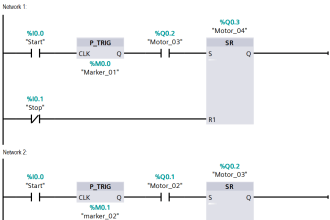
A helpful problem-solving technique is to first identify the necessary coloring which will allow the motor to start up and keep running (i.e. the condition of all permissives during correct operating conditions):

PLC Pump Interlocking

Since the motor is controlled by retentive coil instructions (“Set” and “Reset”), we know all the permissive contacts on the Reset rung must be uncolored in order for the motor to run.

The normally closed “Valve open” instruction must be colored in order to allow the Start input to latch the Set coil and start the motor.

Once we know this, we may determining the necessary “normal” statuses of all permissive switches in order to make their corresponding PLC program contact instructions colored.

A few examples will be given here:

“Valve open” limit switch:

The PLC contact instruction for this permissive is normally-closed, which means that PLC input must be de-energized in order to color that contact instruction.

This means the limit switch must be in the open condition when the valve mechanism moves into the switch’s sensing range (in the fully-open position), and close when the valve mechanism moves away from the switch.

A limit switch that is closed with nothing near it is a normally-closed (NC) limit switch.

Low oil pressure:

The PLC contact instruction for this permissive is normally-closed, which means that PLC input must be energized with electricity in order to maintain that contact instruction in an uncolored state.

This means the low oil pressure switch must be in the closed condition while everything is running as it should (i.e. adequate oil pressure), and open if oil pressure becomes too low.

A pressure switch that is open when pressure is below the trip threshold is a normally-open (NO) pressure switch.

High bearing temperature:

The PLC contact instruction for this permissive is normally-open, which means that PLC input must be de-energized in order to maintain that contact instruction in an uncolored state.

This means the high bearing temperature switch must be in the open condition while everything is running as it should (i.e. low bearing temperature), and close if temperature becomes excessive.

A temperature switch that is open when temperature is below the trip threshold is a normally-open (NO) temperature switch.

Share Your Answer / Comments

Credits : by Tony R. Kuphaldt – under CC BY 1.0

For More PLC Questions : CLICK HERE

If you liked this article, then please subscribe to our YouTube Channel for PLC and SCADA video tutorials.

You can also follow us on Facebook and Twitter to receive daily updates.

Read Next:

  • PLC Electric Motor Interlocks
  • Permissive and Interlock Circuits
  • Troubleshooting PLC Permissive Inputs
  • Basics of Trips, Interlocks, Permissives & Sequences
  • PLC Permissive for Motor Control
Don't Miss Our Updates
Be the first to get exclusive content straight to your email.
We promise not to spam you. You can unsubscribe at any time.
Invalid email address
You've successfully subscribed !

Continue Reading

Allen Bradley Bitwise Logical Operations
How to choose between PLC and DCS Systems ?
Advanced PLC Programming for Defective Parts Sorting
Sorting & Distribution Line PLC Programming – Advanced Logic
What is SCADA System?
The Concept of Shift Register in Omron PLC with Example
Share This Article
Facebook Whatsapp Whatsapp LinkedIn Copy Link
Share
5 Comments
  • Bhargav Reddy says:
    September 3, 2017 at 11:53 am

    Sir
    Difference between DCS & PLC in single line

    Reply
    • S Bharadwaj Reddy says:
      September 3, 2017 at 11:57 am

      Hi, Check these articles. Article 1 Article 2

      Reply
  • Jasim Akram says:
    September 7, 2017 at 3:41 am

    Sir, is there any website through which I can understand instrumentation in Hindi ? If website is exit then please reply me.

    Reply
  • Vikram says:
    July 2, 2019 at 10:08 pm

    Sir,I can’t understand plc program’s,will you get easily simple process is there?

    Reply
  • Brent says:
    July 1, 2020 at 7:43 pm

    Why is vibration contact NC and oil pressure NO?

    Reply

Leave a Reply Cancel reply

Your email address will not be published. Required fields are marked *

Stay Connected

128.3kFollowersLike
69.1kFollowersFollow
210kSubscribersSubscribe
38kFollowersFollow

Categories

Explore More

Timer-Based Sequential PLC Program with One Button
Free InTouch SCADA Tutorial Course for Beginners
PID Simulator Download
Types of Interrupt OB in Siemens Tia Portal
Difference Between Wifi and Industrial Wireless
How CPU Execute Program in Siemens PLC?
Product Sticker Machine with Weighing PLC Program
PLC Structured Text Program for Light Sequences via Timers

Keep Learning

Allen-Bradley PLC Program

Troubleshoot Allen Bradley PLC Logic

Sequential Operation of Output Bits using Two Push buttons

Sequential Operation of Output Bits using Two Push buttons

Calculation of Hydrostatic Pressure

Calculation of Hydrostatic Pressure

What is a function call in TIA Portal

Difference Between FC and FB in Tia Portal

Allen Bradley PLC ControlLogix Hardware

Allen Bradley PLC ControlLogix Hardware

Parts of PLC

Parts of PLC

Top PLC Manufacturers

PLC Brands Software Information

Current-to-Pressure Transducer Calibration Table

Learn More

diode-clamper-circuit

Full Wave Voltage Doubler using Diodes

How to Troubleshoot a PLC System

How to Troubleshoot a PLC System?

PLC Programming for Train Detection and Gate Operation

PLC Programming for Train Detection and Gate Operation

Siemens PLC

Will PLCs become obsolete?

What are Pressure Sensing Lines

What are Pressure Sensing Lines? – Causes of Errors in Measurement

Types of Tripping Protection in MCCB

Types of Tripping Protection in MCCB

PLC Programming Classroom Bell System

Classroom Bell System – PLC Programming Practice Examples

Dew Point Meter Principle

Dew Point Meter Principle

Menu

  • About
  • Privacy Policy
  • Copyright

Quick Links

  • Learn PLC
  • Helping Hand
  • Part Time Job

YouTube Subscribe

Follow US
All rights reserved. Reproduction in whole or in part without written permission is prohibited.
Welcome Back!

Sign in to your account

Username or Email Address
Password

Lost your password?