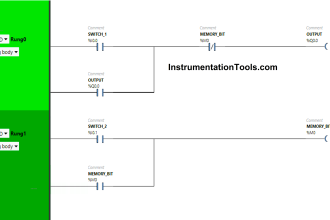
The Process Control system may provide steady state or change of state (start-up, shutdown, batch) control functions. The latter may be implemented by automatic sequences or procedurally under manual control.
Control systems should be implemented to provide stable control of the process under all expected normal and upset circumstances, including start-up and shutdown.
The system should be designed to prevent or verify operator commands which might place a demand upon the protective system.
Process control systems are primarily implemented for economic reasons. However, those which are not considered safety related should still be designed, installed, operated and maintained so that their failure does not place a rate demand in the protective system which was not anticipated in its design. Part 1 of IEC 61508 provides guidance.
The dangerous failure modes of the control system should be determined and taken into account in overall safety system specification. The control system should also be sufficiently independent of the safety systems.
The dangerous failure rate of the control system should be supported by operational experience of the system in a similar application, reliability analysis or reliability data from industry databases.
The failure rate that may be claimed may not be less than 10-5 dangerous failures/hour.
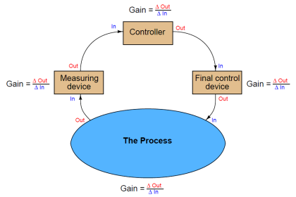
Process Control System
Consideration should be given to failure behaviour so as to minimise the demands placed on the protective systems such as under the following circumstances:
- I/O power failure;
- Main power failure;
- I/O faults (open/short circuit, out of range);
- Module/processor failure (I/O, controller, cell, supervisory);
- Communications failure (at all levels of the architecture).
Consideration should also be given to change control and software back-up systems. As the control system provides control, monitoring and logging functions which significantly aid the operator, consideration should be given to survival of the control system during hazardous events and emergency response.
It should be noted that redundant (non-diverse), cross monitored control processors are extremely vulnerable to common mode failure.
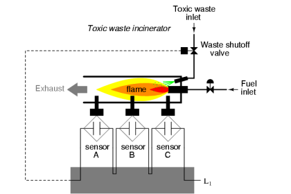
It should be demonstrated that the process control system does not exercise safety functions during sequences and changes of state under its control.
For example, where the control system batch sequence controls the mixing of quantities of materials or reagents which, if incorrect quantities are admitted, may result in an unintended reaction, then measures of sufficient safety integrity, other than the control system, should be taken to ensure that the residual risk is as low as reasonable practicable.
For the purposes of risk evaluation, failure of the control system (at not less than 10-5 failures/hour or 10-1 failures on demand) should be considered as part of the hazard initiation sequence rather than a risk reduction measure.
Exothermic reactions
Exothermic reactions are particularly demanding in terms of control and protection as they tend to be unstable with aggressive reaction kinetics, and may require risk reduction measures which are required continuously throughout the reaction stage and which rely on utilities such as cooling systems, agitation, inhibitor injection etc.
Thus, loss of any single utility may be a dangerous failure, and initiate a hazard (e.g. loss of agitator blades, and hence reduced cooling because of poorer heat transfer, giving rise to a runaway reaction).
The components of the utilities should be considered safety related and provide adequate protection against failure including common mode failures (e.g. loss of electricity) and systematic failures (e.g. failure to fill inhibitor stock vessel). Sufficient diagnostics should be provided to reveal such failures so that timely automatic or manual response can be initiated.
Diagnostics should be designed to reveal the failure as directly as possible, for example:
- Agitator torque rather than shaft speed (which will not reveal blade loss);
- Cooling water flow rather than pump stopped.
Their capacity and capability to deal with the most extreme reaction kinetics (e.g. worst case mixtures) and limiting conditions (e.g. maximum temperature/pressure achievable under worst case) should also be demonstrated.
Note : Contains public sector information licensed under Open Government Licence v3.0.


will you help me to explain how startup, shutdown, and batch works