Inst ToolsInst ToolsInst Tools
  • Courses
  • Automation
    • PLC
    • Control System
    • Safety System
    • Communication
    • Fire & Gas System
  • Instrumentation
    • Design
    • Pressure
    • Temperature
    • Flow
    • Level
    • Vibration
    • Analyzer
    • Control Valve
    • Switch
    • Calibration
    • Erection & Commissioning
  • Interview
    • Instrumentation
    • Electrical
    • Electronics
    • Practical
  • Q&A
    • Instrumentation
    • Control System
    • Electrical
    • Electronics
    • Analog Electronics
    • Digital Electronics
    • Power Electronics
    • Microprocessor
  • Request
Search
  • Books
  • Software
  • Projects
  • Process
  • Tools
  • Basics
  • Formula
  • Power Plant
  • Root Cause Analysis
  • Electrical Basics
  • Animation
  • Standards
  • 4-20 mA Course
  • Siemens PLC Course
Reading: Why Pressure Vessel Connected to Tubing System?
Share
Notification Show More
Font ResizerAa
Inst ToolsInst Tools
Font ResizerAa
  • Courses
  • Design
  • PLC
  • Interview
  • Control System
Search
  • Courses
  • Automation
    • PLC
    • Control System
    • Safety System
    • Communication
    • Fire & Gas System
  • Instrumentation
    • Design
    • Pressure
    • Temperature
    • Flow
    • Level
    • Vibration
    • Analyzer
    • Control Valve
    • Switch
    • Calibration
    • Erection & Commissioning
  • Interview
    • Instrumentation
    • Electrical
    • Electronics
    • Practical
  • Q&A
    • Instrumentation
    • Control System
    • Electrical
    • Electronics
    • Analog Electronics
    • Digital Electronics
    • Power Electronics
    • Microprocessor
  • Request
Follow US
All rights reserved. Reproduction in whole or in part without written permission is prohibited.
Inst Tools > Blog > Practical Questions > Why Pressure Vessel Connected to Tubing System?

Why Pressure Vessel Connected to Tubing System?

Last updated: September 17, 2020 5:46 pm
Editorial Staff
Practical Questions
No Comments
Share
3 Min Read
SHARE

A very useful principle in physics is the Ideal Gas Law, so called because it relates pressure, volume, molecular quantity, and temperature of an ideal gas together in one neat mathematical expression:

PV = nRT

Where,

P = Absolute pressure (atmospheres)

V = Volume (liters)

n = Gas quantity (moles)

R = Universal gas constant (0.0821 L · atm / mol · K)

T = Absolute temperature (K)

Although this “law” is not perfectly accurate for real gases, especially at high pressures and/or near the point of liquefaction, it is quite accurate for air near ambient temperature and pressure.

One very practical application of this law is found in a method for generating low air pressures such as those easily measured by water- or oil-based manometers.

Most mechanical air compressors generate pressures far exceeding the range of all but the largest manometers.

Though it is possible to purchase precision pressure regulators for reducing such large pressures down to a level measurable by a manometer, these devices are expensive. An alternative is to generate the air pressure with a hand pump (such as a bicycle tire pump) connected to a relatively large pressure vessel:

pressure transmitter calibration setup

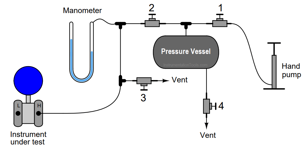
Without the volume of the pressure vessel connected to the tubing system, the air pressure would increase dramatically for each stroke of the air pump. With the pressure vessel connected, each pump stroke contributes a much smaller amount of additional pressure to the system. Use the Ideal Gas Law equation to explain why this is.

Answer:

Actuating the hand pump introduces more air molecules to the system (n).

Assuming temperature (T) remains constant, the air pressure (P) will increase in inverse proportion to the volume (V ) of the pressure vessel for each additional stroke of the pump.

More Questions for You:

Follow-up question: If we wished the pressure to increase less for every stroke of the pump, would we want a smaller pressure vessel or a larger pressure vessel? Explain your answer.

Challenge question: suppose a technician follows these steps in using this system.

  • Close valve 2, open valves 1 and 3
  • Pump several strokes’ worth of air into the pressure vessel
  • Close valves 1 and 3
  • Slowly open valve 2 until manometer registers desired pressure, then close

Is the air pressure going to the instrument under test greater than, less than, or equal to the air pressure in the vessel?

Share your answers with us through below comments section.

Read Next:

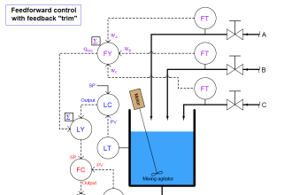
  • Chemical Reactor Vessel P & ID
  • Pneumatic Instrumentation
  • Hydrostatic Level Transmitter
  • Transmitter impulse lines
  • Air Pressure Inside the Tank

Credits: Tony Kuphaldt

Don't Miss Our Updates
Be the first to get exclusive content straight to your email.
We promise not to spam you. You can unsubscribe at any time.
Invalid email address
You've successfully subscribed !

Continue Reading

Questions on Level Switches
Identify the Purpose of Flow Ratio Controller
Instrument Lab Exercise – Ranging and Manometer Usage
Pneumatic Moment-balance Differential Pressure Transmitter
Why Strain Gauge Resistance Changes as it Stretches and Shrinks?
Programmable Logic Controller (PLC) Questions and Answers – 3
Share This Article
Facebook Whatsapp Whatsapp LinkedIn Copy Link
Share
Leave a Comment

Leave a Reply Cancel reply

Your email address will not be published. Required fields are marked *

Stay Connected

128.3kFollowersLike
69.1kFollowersFollow
210kSubscribersSubscribe
38kFollowersFollow

Categories

Explore More

Which Tube has most Hydrostatic Pressure?
Smart DP Transmitter Flow Meter Calculations
PLC Permissive for Motor Control
Which Instrument is at Fault in this System?
Baffle Nozzle Assembly Sensitive Mechanism
Hydrostatic Level Transmitter Questions
PLC Programming Question & Answer
How to Connect Proximity Switch (Sink Type) to Make LED ON ?

Keep Learning

Pneumatic Transmitter

Questions on Pneumatic Transmitter and Repeater

Simple High Level Indicator Circuit

Simple High Level Indicator Circuit

DP Transmitter Block and Bleed Valve

DP Transmitter Block and Bleed Valves

Hydraulic Actuated Lift

Oil and Air Pressure Actuated Lifts Questions

A span error with wrong slope

Determine the Instrument Calibration Error

Problem on Tachogenerator

Problem on Tachogenerator

Type E thermocouple

Type E thermocouple Calculations

PLC Program for Valves

PLC Pump Permissive Interlocks

Learn More

Power Systems Questions & Answers

Power Systems MCQ Series 7

Synchronous Generator Salient Pole vs Non Salient Pole

Pressure Control Valve

What is Pressure Control Valve?

Calibration Procedure of displacer type Level transmitter

Calibration of Displacer Level Transmitter

Comparison of MOSFET and BJT

Comparison of MOSFET and BJT

hard disk drive

Difference Between HDD and SSD

Electronic Devices & Circuits Objective Questions

Electronic Devices & Circuits Quiz – Set 11

PLC Program for Alarm Indication in Process

PLC Program for Alarm Indication in Process Control

Menu

  • About
  • Privacy Policy
  • Copyright

Quick Links

  • Learn PLC
  • Helping Hand
  • Part Time Job

YouTube Subscribe

Follow US
All rights reserved. Reproduction in whole or in part without written permission is prohibited.
Welcome Back!

Sign in to your account

Username or Email Address
Password

Lost your password?