Inst ToolsInst ToolsInst Tools
  • Courses
  • Automation
    • PLC
    • Control System
    • Safety System
    • Communication
    • Fire & Gas System
  • Instrumentation
    • Design
    • Pressure
    • Temperature
    • Flow
    • Level
    • Vibration
    • Analyzer
    • Control Valve
    • Switch
    • Calibration
    • Erection & Commissioning
  • Interview
    • Instrumentation
    • Electrical
    • Electronics
    • Practical
  • Q&A
    • Instrumentation
    • Control System
    • Electrical
    • Electronics
    • Analog Electronics
    • Digital Electronics
    • Power Electronics
    • Microprocessor
  • Request
Search
  • Books
  • Software
  • Projects
  • Process
  • Tools
  • Basics
  • Formula
  • Power Plant
  • Root Cause Analysis
  • Electrical Basics
  • Animation
  • Standards
  • 4-20 mA Course
  • Siemens PLC Course
Reading: PLC Techniques for I/O Mapping
Share
Font ResizerAa
Inst ToolsInst Tools
Font ResizerAa
  • Courses
  • Design
  • PLC
  • Interview
  • Control System
Search
  • Courses
  • Automation
    • PLC
    • Control System
    • Safety System
    • Communication
    • Fire & Gas System
  • Instrumentation
    • Design
    • Pressure
    • Temperature
    • Flow
    • Level
    • Vibration
    • Analyzer
    • Control Valve
    • Switch
    • Calibration
    • Erection & Commissioning
  • Interview
    • Instrumentation
    • Electrical
    • Electronics
    • Practical
  • Q&A
    • Instrumentation
    • Control System
    • Electrical
    • Electronics
    • Analog Electronics
    • Digital Electronics
    • Power Electronics
    • Microprocessor
  • Request
Follow US
All rights reserved. Reproduction in whole or in part without written permission is prohibited.
Inst Tools > Blog > PLC Tutorials > PLC Techniques for I/O Mapping

PLC Techniques for I/O Mapping

Learn about PLC techniques for I/O mapping for four types - digital inputs, digital outputs, analog inputs, and analog outputs.

Last updated: September 16, 2024 6:02 am
Viral Nagda
PLC Tutorials
No Comments
Share
5 Min Read
SHARE

When you are writing a PLC program, the very first thing that you have to do is map the inputs and outputs (IO). PLC digital and analog IO’s must be given proper tag conventions because that defines their proper use in the remainder of the program further.

Contents
What does it mean to map I/O in PLC?Types of I/O mapping in PLCMapping I/O tags at hardware configurationMapping I/O tags manually in the program

If the IO’s are not mapped and named properly according to actual field instruments, then the programmer will get confused in developing the logic afterward. There are some common and general methods which need to be followed for doing proper IO mapping in a PLC program. In this post, we will see the techniques for IO mapping in PLC.

What does it mean to map I/O in PLC?

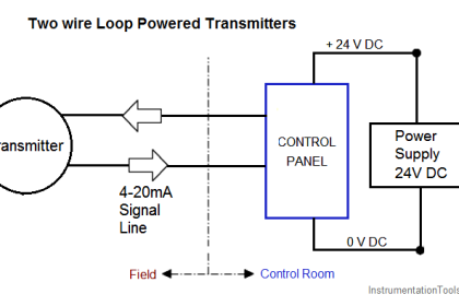
PLC has four types of I/O’s – digital inputs, digital outputs, analog inputs, and analog outputs. They are connected in PLC in various electrical signals like 24V DC, 24V AC, 230V AC, 4-20 mA, 0-10V, RTD, or thermocouple. They are then converted to digital signals inside the PLC to make the processor understand.

Now, when you configure IO in PLC, you define the number of points to use, configure the type of analog IO, and configure the scaling of analog IO. After that, the next step comes in naming these IOs according to their corresponding convention.

Once the naming is done, you can either move these values to some internal memory words or use them directly in the program. This is called I/O mapping in PLC.

Types of I/O mapping in PLC

The main types of input-output mapping are mentioned below.

  • Mapping I/O tags at hardware configuration
  • Mapping I/O tags manually in the program

Mapping I/O tags at hardware configuration

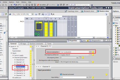
Let us see the first step which is very easy to use. As the name says, we can directly map the tags in the hardware configuration. Refer to the below image.

PLC Technique for IO Mapping

You can see that the first two inputs, I0 and I1, have been named as I_EmgStop and I_StartPb respectively. The first two outputs, Q0 and Q1, have been named as Q_Lamp and Q_Motor respectively. You can use these tag names in the program directly.

Suppose input-1 is on; then the tag – I_EmgStop will be 1. When the input-1 is off; then the tag – I_EmgStop will be 0. Similarly, if you want to turn on the physical hardware output Q0, then just write value 1 to the tag – Q_Lamp.

So, there is no need to write extra logic of moving the by default names of IO’s in a separate variable, which will be the IO name. This saves memory as well as reduces the troubleshooting period.

Mapping I/O tags manually in the program

The other technique we will discuss is writing a logic to assign tags for IOs. As discussed in the first part, the technique saves memory and makes troubleshooting easier. But this is good for a small application. If you have a large application where there are hundreds of IOs, then configuring tags in the hardware will take time as you have to configure each input or output separately.

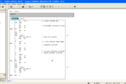
For this, it is better to write a logic. Refer to the below image. For best performance, use structured text language in the PLC program. Why? We will discuss this further in the post.

Types of IO mapping in PLC

As seen in the image, if you see the first line, it is written like we are moving the value of physical address %IX0.0 to a variable named I_EmgStop. This means, that whatever the status of the input, the same will be moved in that variable. A similar PLC logic is written for the remaining inputs. You can then use these tags in your program, which will reflect IO values.

The main advantage of ST language is that you can write the logic in Excel and just copy it from there. Mostly, big automation systems have the same types of field instruments with repetitive names. So, dragging the names and copying them from Excel makes the task easier.

Mapping IO tags at PLC hardware configuration

In this way, we saw the techniques for I/O mapping in PLC.

Read Next:

  • Intro to Mitsubishi Electric GOC Controllers
  • Tanks Draining Control in PLC Programming
  • Intrinsically Safe Barriers Questions and Answers
  • Structured Text for Measuring Event Duration
  • PLC FBD Example for Tank Liquid Heating Logic

Don't Miss Our Updates
Be the first to get exclusive content straight to your email.
We promise not to spam you. You can unsubscribe at any time.
Invalid email address
You've successfully subscribed !

Continue Reading

Create Logic with InTouch Scada using Scripting
200+ Quiz on Electrical Meters, Measurement, and Troubleshooting
OB1 – Main Cyclic Organization Block in TIA Portal
PLC or DCS Control System Spares
How to Use Diagnostic Buffer for SIEMENS PLC?
How to use PLC with SQL Database? – Basics & Tutorials
Share This Article
Facebook Whatsapp Whatsapp LinkedIn Copy Link
Share
Leave a Comment

Leave a Reply Cancel reply

Your email address will not be published. Required fields are marked *

Stay Connected

128.3kFollowersLike
69.1kFollowersFollow
210kSubscribersSubscribe
38kFollowersFollow

Categories

Explore More

Do’s and Don’ts in PLC
Single-acting Cylinder OR Logic Operation (PLC and Sensors)
PLC Programming Example for a Batch Process
PLC Ladder Logic for Lube Oil Pump Motor
PLC Timer Instructions
What is Marshalling Cabinet?
Yokogawa DCS and SIS System Architecture
PLC Cooking Timer Example for Kitchen Automation

Keep Learning

Can a PLC Function Without an HMI or SCADA

Can a PLC Function Without an HMI or SCADA?

Move function block

Move Instruction in Tia Portal

DCS Commissioning Steps

DCS Commissioning Steps

Statement List (STL) to Find Highest Value in the Data Block

Statement List (STL) to Find Highest Value

PLC Project Examples for EcoStruxure Machine Expert

PLC Project Examples for EcoStruxure Machine Expert

Ladder Logic Programming Examples

Ladder Logic Programming Examples

Types of Interrupts Organization Blocks in Tia Portal

Types of Interrupt OB in Siemens Tia Portal

PLC Automatic Irrigation System Ladder Logic Project

PLC Automatic Irrigation System

Learn More

Safety interlock for motor starters in Siemens PLC

Motor Starter Logic using Siemens PLC Tia Portal

Water Vapor in Instrument Air Lines

How to Minimize Water Vapor in Instrument Air Lines?

Flow Element Symbol

What is a Flow Element? – Types, Comparison of Flow Elements

Hydrogen Sulfide Accident

The Aghorn Hydrogen Sulfide Accident – H2S Gas

Pressure Measurement Multiple Choice Questions

Relay Circuit for Hooter with Reset Button

Relay Latching Circuit using Push Button

Packaging Machinery

Poor Bagging Scale Availability Threatened Production Cuts

Shaft and Coupling Bore Tapers Repair Caused Frequent Shutdowns

Shaft and Coupling Bore Tapers Repair Caused Frequent Shutdowns

Menu

  • About
  • Privacy Policy
  • Copyright

Quick Links

  • Learn PLC
  • Helping Hand
  • Part Time Job

YouTube Subscribe

Follow US
All rights reserved. Reproduction in whole or in part without written permission is prohibited.
Welcome Back!

Sign in to your account

Username or Email Address
Password

Lost your password?