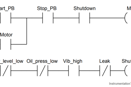
Develop a PLC program that will simulate the gate array logic as shown in the below figure.
Gate Array Logic
Simulate the given gate array logic in ladder logic operation.

Program Logic
Totally there are 10 digital inputs and one digital output.
Solve each OR block separately, do the two AND Function and finally do the OR operation at the end.
Input-Output List

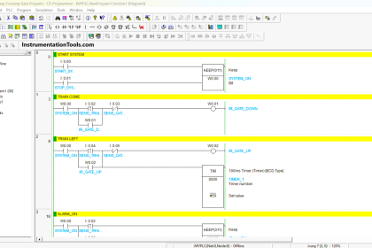
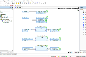
PLC Program for Gate Array Logic

Program Description
RUNG 0000
A, C AND INVERTED B are into OR operation. D and E are into OR operation.
Those two results will make AND operation with G and inverted F.
The Final result is stored in memory coil B3:0/0.
RUNG 0001
H and I are into OR operation and the result is AND with J.
The final result is stored in memory coil B3:0/1.
RUNG 0002
B3:0/0 and B3:0/1 are into OR operation to enable or disable output Y.
PLC Programming Simulation
CASE 1:
When anyone rung goes true output Y turns ON.

CASE 2:
When anyone rung goes true output Y turns ON.

CASE 3:
When both rungs goes false output Y is disabled.

Conclusion:
The above-explained logic for gate array logic and is successfully simulated with three case studies.
If you liked this article, then please subscribe to our YouTube Channel for PLC and SCADA video tutorials.
You can also follow us on Facebook and Twitter to receive daily updates.
Read Next:
Data Handling Instructions in PLC
Ladder Logic Example with Timer