Inst ToolsInst ToolsInst Tools
  • Courses
  • Automation
    • PLC
    • Control System
    • Safety System
    • Communication
    • Fire & Gas System
  • Instrumentation
    • Design
    • Pressure
    • Temperature
    • Flow
    • Level
    • Vibration
    • Analyzer
    • Control Valve
    • Switch
    • Calibration
    • Erection & Commissioning
  • Interview
    • Instrumentation
    • Electrical
    • Electronics
    • Practical
  • Q&A
    • Instrumentation
    • Control System
    • Electrical
    • Electronics
    • Analog Electronics
    • Digital Electronics
    • Power Electronics
    • Microprocessor
  • Request
Search
  • Books
  • Software
  • Projects
  • Process
  • Tools
  • Basics
  • Formula
  • Power Plant
  • Root Cause Analysis
  • Electrical Basics
  • Animation
  • Standards
  • 4-20 mA Course
  • Siemens PLC Course
Reading: Series Tanks Level Control using PLC Ladder Programming
Share
Notification Show More
Font ResizerAa
Inst ToolsInst Tools
Font ResizerAa
  • Courses
  • Design
  • PLC
  • Interview
  • Control System
Search
  • Courses
  • Automation
    • PLC
    • Control System
    • Safety System
    • Communication
    • Fire & Gas System
  • Instrumentation
    • Design
    • Pressure
    • Temperature
    • Flow
    • Level
    • Vibration
    • Analyzer
    • Control Valve
    • Switch
    • Calibration
    • Erection & Commissioning
  • Interview
    • Instrumentation
    • Electrical
    • Electronics
    • Practical
  • Q&A
    • Instrumentation
    • Control System
    • Electrical
    • Electronics
    • Analog Electronics
    • Digital Electronics
    • Power Electronics
    • Microprocessor
  • Request
Follow US
All rights reserved. Reproduction in whole or in part without written permission is prohibited.
Inst Tools > Blog > PLC Tutorials > Series Tanks Level Control using PLC Ladder Programming

Series Tanks Level Control using PLC Ladder Programming

We need to control level of tanks which are connected in series. Implement program for Series Tanks Level Control using PLC Ladder Programming.

Last updated: November 3, 2023 11:50 am
Editorial Staff
PLC Tutorials
No Comments
Share
3 Min Read
SHARE

We need to control the level of tanks which are connected in series. Implement program for Series Tanks Level Control using PLC Ladder Programming.

Contents
Series Tanks Level ControlProblem DiagramProblem SolutionList of Inputs and OutputsPLC Ladder Diagram for Level control of Series TanksProgram DescriptionResult

Series Tanks Level Control

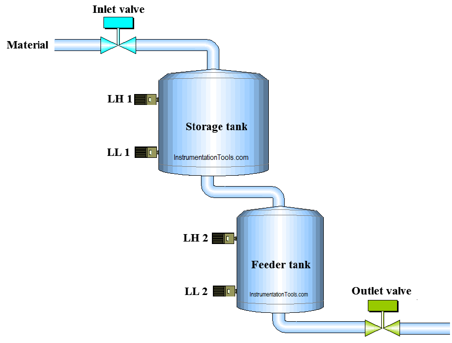
Two tanks are connected in series connection. We need to control of both tanks which are connected in series.

Implement the PLC program for this application.

Problem Diagram
PLC Program to Control Level of Series Tanks

Problem Solution

In chemical companies, there are lots of materials which are used for process and also stored in storage tanks for different processes.

Here we consider two tanks, 1. Storage Tank and 2. Feeder Tank.

Storage tank has more capacity than feeder tank. Storage tank is for material storage and feeder tank is for material supply for other process.

Two level switches are used for level detection and one inlet valve for material feeding control.

Consider one manual outlet valve and it can be operated as per requirement by the operator.

For this application we can use PLC, we will write PLC program for this application.

List of Inputs and Outputs

Digital Inputs

  • Cycle START :- I0.0
  • Cycle STOP :- I0.1
  • Low level storage tank (LL1) :- I0.3
  • Low level feeder tank (LL2) :- I0.4
  • High level storage tank (LH1) :- I0.5
  • High level feeder tank (LH2) :- I0.6

Digital Output

  • Inlet valve :- Q0.0

M memory

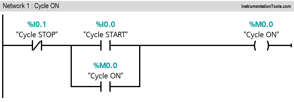
  • Cycle ON bit :- M0.0
  • Inlet valve close condition :- M0.1

PLC Ladder Diagram for Level control of Series Tanks
PLC Ladder Series Tank
PLC Tank Ladder Program
Series Tank PLC Logic

Program Description

For this application we used S7-300 PLC and TIA portal software for programming. We can implement this logic by using other PLC also.

Network 1:

Network 1 is for latching circuit. Whenever START button is pressed (I0.0), Cycle ON (M0.0) bit will be ON. Cycle can be STOP by pressing STOP PB (I0.1).

Network 2:

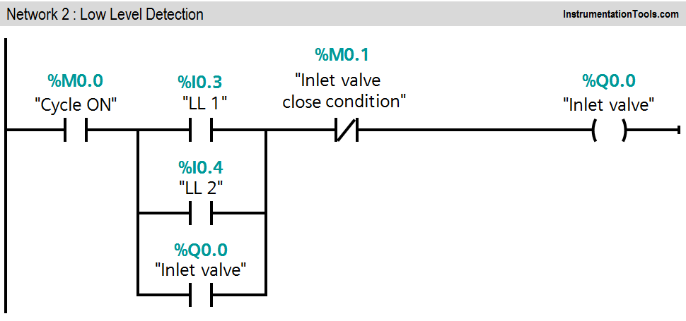
If low level of storage tank (I0.3) or low level of feeder tank (I0.4) is detected, inlet valve (Q0.0) will be ON. (Inlet valve close condition should not present).

Network 3:

High levels (I0.5 &I0.6) of both tanks are detected, inlet valve close condition will be activated and it will close the inlet valve (Q0.0). Here outlet valve is manual valve, it can be operated by operator as per requirement.

Note :- Above application may be different from actual application. This example is only for explanation purpose only. We can implement this logic in other PLC also.

Result

Series Tank Ladder Logic

Author : Bhavesh

If you liked this article, then please subscribe to our YouTube Channel for PLC and SCADA video tutorials.

You can also follow us on Facebook and Twitter to receive daily updates.

Read Next:

  • PLC Controls a Motor?
  • Three Element Drum Level Control
  • Water Level Monitoring System
  • Latching and unlatching Circuit
  • PLC Memory Mapping
Don't Miss Our Updates
Be the first to get exclusive content straight to your email.
We promise not to spam you. You can unsubscribe at any time.
Invalid email address
You've successfully subscribed !

Continue Reading

Elevator PLC Ladder Logic
Things to Take Care of When Designing SCADA System
What is a Relay? Types of Industrial Relays
PLC Programming for Tank Heating Control using Heater
GET Command – Siemens PLC-to-PLC Communication Project
Difference Between PLCSIM and PLCSIM Advanced? – Siemens PLC
Share This Article
Facebook Whatsapp Whatsapp LinkedIn Copy Link
Share
Leave a Comment

Leave a Reply Cancel reply

Your email address will not be published. Required fields are marked *

Stay Connected

128.3kFollowersLike
69.1kFollowersFollow
210kSubscribersSubscribe
38kFollowersFollow

Categories

Explore More

Always ON and OFF Bit using Ladder Logic and Statement List
How to Interchange ON Delay Timer and OFF Delay Timer in a PLC
PLC Programming Example for a Batch Process
Programmable Logic Controller Quiz
Peripheral Inputs and Outputs in Siemens PLC
VFD Commissioning and Testing Procedure (Variable Frequency Drive)
PLC Ladder Logic Questions and Answers
Light ON OFF Control using PLC

Keep Learning

Cyclic Interrupts TIA Portal

Configuring and Usage of Cyclic Interrupts TIA Portal (OB 30+)

Single-acting Pneumatic Cylinder operation with Limit Switch

Single-acting Pneumatic Cylinder Operation with Limit Switch

PLC Program using Timers

PLC Timers Program

PLC Ladder Logic Chemical Mixing Process

Chemical Mixing Process using PLC

Free Mitsubishi PLC Online Training Courses

Free Mitsubishi PLC Online Training Course and Tutorials

Run 4 Motors Sequentially from Same Push button PLC Program

Run 4 Motors Sequentially from Same Push button PLC Program

How to Select a SCADA for New Project

How to Select a SCADA for New PLC Project?

Node-RED in PLC Automation

Node-RED in PLC Industrial Automation

Learn More

Measurement Unit Conversions

Measurement Unit Conversions

gas chromatograph (GC)

Industrial Applications of Chromatographs

Stepper Motor Working Principle Animation

Stepper Motor Working Principle

Combining Independent Current Sources in Parallel

Combining Independent Current Sources in Parallel

PLC Program for Alarm Indication in Process

PLC Program for Alarm Indication in Process Control

PLC Temperature Control using Pulse Width Modulation

PLC Temperature Control using Pulse Width Modulation (PWM)

Digital Electronics Multiple Choice Questions

Random Access Memory Objective Questions – Part 3

What is OTDR Testing

Understanding the Difference between HOP Test and OTDR

Menu

  • About
  • Privacy Policy
  • Copyright

Quick Links

  • Learn PLC
  • Helping Hand
  • Part Time Job

YouTube Subscribe

Follow US
All rights reserved. Reproduction in whole or in part without written permission is prohibited.
Welcome Back!

Sign in to your account

Username or Email Address
Password

Lost your password?