This is PLC Program for Two ways switch logic for staircase light in house
PLC Two Way Switch Logic
In duplex type house there are ground floor and first floor and sometimes second floor also.
Sometimes people need to go from ground floor to first floor or from first floor to ground floor by staircase provided in house.
But in staircase there is no sunlight so people need a lamp/light to see the steps of the staircase easily.
Here we are using a simple PLC to control this lamp using two switches, one switch at ground floor and second switch at first floor to control one lamp as shown in below figure.
Note : we can also build the circuit using simple relays/switches also. This article only for understanding the basic concept of 2 way switch using a PLC Ladder Logic.
Image

Solution
We will solve this problem by simple automation. As shown in figure consider one simple house with one floor and staircase is provided in the house.
Here we will set lighting system for the users to switch ON/OFF the light whether they are on bottom of the stair or at top.
We will provide separate switch for each floor as shown in above figure.
PLC I/O Requirements
Digital Inputs
- SW1 : I0.1
- SW2 : I0.2
Digital Outputs
- Lamp : Q0.0
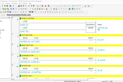
PLC Progam for Two-way Switch

Program Explained
- For this application, we used S7-1200 PLC and TIA portal software for programming.
- In above program, we have added two NO contacts of SW 1 (I0.1) and SW 2 (I0.2) in series and NC contacts of SW1 (I0.1) and SW2 (I0.2) in parallel of this series SW1 & SW2 NO Contacts.
- If the status of the bottom switch (SW1) and status of the top switch (SW2) are same then lamp will be ON. And if either status of the bottom or top switch is different from other then lamp (Q0.0) will be OFF.
- When lamp (Q0.0) is OFF then user can ON the lamp by changing status of any switch. Also user can turn OFF the lamp by changing the status of one of the two switches.
Result

Note: The above PLC Logic provided for basic idea about application of PLC for Two Way Switch Logic. The Logic is limited and not complete application.
If you liked this article, then please subscribe to our YouTube Channel for PLC and SCADA video tutorials.
You can also follow us on Facebook and Twitter to receive daily updates.
Read Next:
- PLC Ladder Logic: Contacts and coils
- Sequence of Conveyors with Interlock
- Two out of Three Logic Analogy
- Float-type Level Switch to Control a pump
- Programmable Logic Controllers MCQ


I think this LD is wrong.There must be SW1 (NO) to SW2(NC) (1st rung)
SW2(NO) to SW1(NC)(2 nd rung)
I THINK IT SHOULD BE XOR GATE