Design a PLC program for an alternate output circuit with a latched function and explain the ladder logic with a solution.
Alternate Output Circuit
Problem Description
Setting the light ON by pressing a SWITCH on 1st time, 3rd time, 5th time etc. and setting the same light OFF by pressing the SWITCH by 2nd time , 4th time, 6th time etc.
Restore the output status to “0” when system or cycle power up. Output can be START by pressing a BUTTON in ODD number of times and can be STOP by pressing the same BUTTON by EVEN number of times.
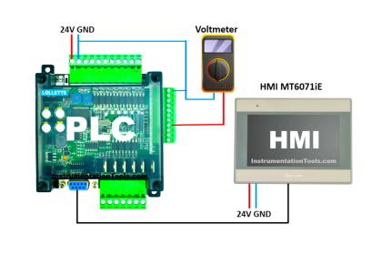
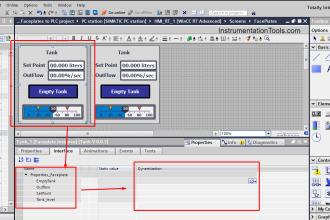
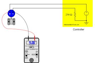
Problem Diagram

Problem Solution
We can solve this problem by using simple Ladder logic. In this we consider one simple example of alternate LED operation.
Here we consider one LED and one BUTTON. Press the BUTTON alternately and output should be ON/OFF alternately, here during the Button pressed odd number times then output should be ON and during the button pressing even number of times then the output should be OFF.
List of PLC Inputs & Outputs
Inputs List
- SWITCH : I0.0
Output List
- LED : Q0.0
M Memory
- M0.0 for LED reset condition
- M0.1 for counter reset
- M11.0 & M11.1 – Positive edge
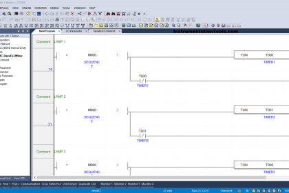
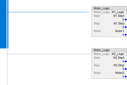
Ladder Diagram for alternate output circuit (with latched function)
PLC Program Description
In this application, we have used Siemens S7-300 PLC and TIA Portal Software for programming.
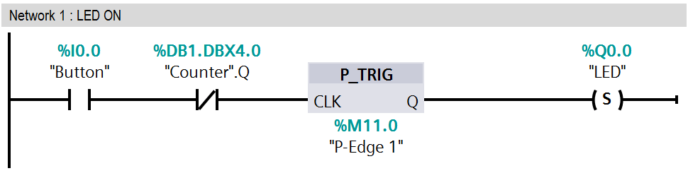
Network 1:
In network 1 we have used SET instruction to set the LED (Q0.0). Here we have taken NO contact of BUTTON (I0.0)
so LED (Q0.0) can be activated by pressing BUTTON (I0.0).
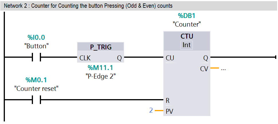
Network 2:
Here we used a counter so it will count the switching times of the BUTTON (I0.0).
This counter will tell us about the number of times the button is pressed, its value or the value is a EVEN number or ODD number.
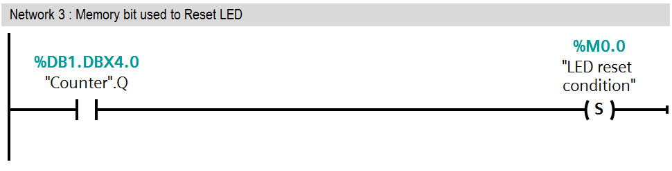
Network 3:
When counter will reach its preset value (2) or say EVEN number of times, NO contact of the counter will set the M0.0 (LED reset condition).
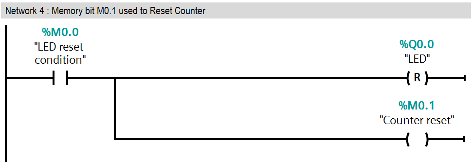
Network 4:
In this network NO contact of the M0.0 will RESET the LED and counter.
Here M0.1 (counter reset memory) will RESET the counter.
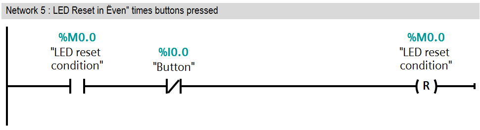
Network 5:
If M0.0 is ON and negative transition (from 1 to 0) of button (I0.0) will be triggered then RESET condition of LED will be OFF.
Note : This example is provided to understand the basic concept of alternate output circuit, it is not full application but we can use this concept in any automation application or any system.
Test Cases

If you liked this article, then please subscribe to our YouTube Channel for PLC and SCADA video tutorials.
You can also follow us on Facebook and Twitter to receive daily updates.
Read Next:
- Setpoints and Alarms
- PLC Digital Signals Wiring
- Free SCADA Software
- PLC Contacts and coils
- Control Room Interview Questions