Develop a PLC program for 2 push buttons to control 1 output to turn ON or OFF as per the logic.
Note: This PLC logic is prepared for learning purposes to help users learn ladder logic programming.
2 Push buttons to Control 1 Output
Problem Statement:
Design a PLC ladder logic for the following application.
We are using two push buttons to control the output.
When Push Button 1 is Pressed and then Released, then Output will be ON.
When Push Button 2 is Pressed and then Released, then Output will be OFF.
PLC Program
This PLC program video explains the complete logic development for this problem.
Inputs and Outputs
Digital Inputs:
Push Button 1: I0.0
Push Button 2: I0.1
Digital Output:
Output: Q0.0
Memory Bit
Memory Bit: M0
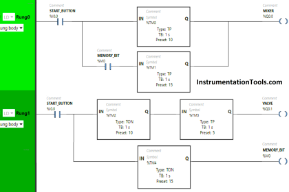
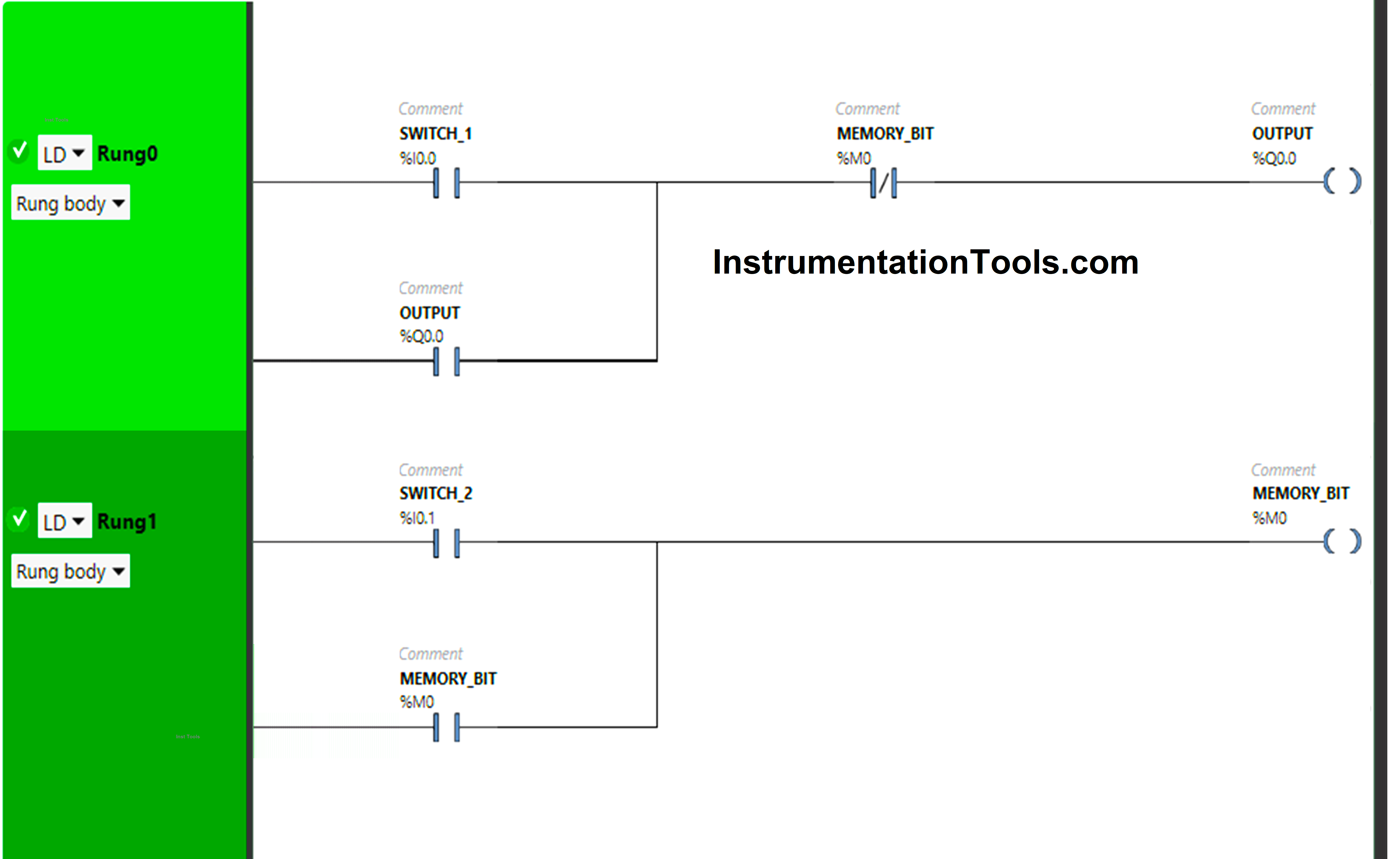
Ladder Logic
Program Explanation
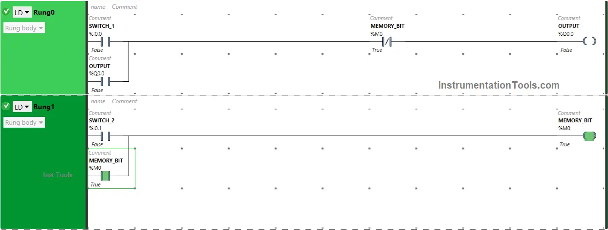
We have used Normally Open Contacts as well Normally Closed Contact and Memory Bits.
Normally Closed Contact is used for Memory Bit in Rung0.
When Push Button 1 is pressed, Output will turn ON.
Output still remains ON, When Push Button 1 is released because of Latching used for Output in Rung0.
When Push Button 2 is pressed, Memory Bit will turn ON and Output will turn OFF as Normally Closed Contact used for Memory Bit in Rung0 will be in true state. In true state, Normally Closed Contact does not allow the signal to pass to the Output.
Output still remains OFF, when Push Button 2 is Released as Memory Bit is connected with Push Button 2 in Rung1, and Push Button 2 in Rung0 will remain in True State because Latching is used for Memory Bit in Rung1. So, Normally Closed Contact used for the Memory Bit in Rung0 also will remain in its true state and will not allow the signal to pass to the Output.
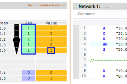
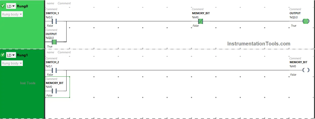
Simulation Result
Now test our logic and discuss the simulation results.
When Push Button 1 is PRESSED

The signal flows through Push Button 1 as it is in true state and Output will turn ON.
In a false state, Memory Bit in Rung0 also passes the signal to turn ON the Output as Normally Closed Contact is used for Memory Bit in Rung0.
When Push Button 1 is RELEASED
When Push Button I is released, Output will remain ON as Latching is used for the Output in Rung0.
When Push Button 2 is PRESSED

Pressing Push Button 2 will turn OFF the Output because Memory Bits in Rung0 and Rung1 will turn ON.
So, Normally Closed Contact used for the Memory Bit in Rung0 will be in a true state and does not allow the signal to pass to the Output.
When Push Button 2 is RELEASED
As Latching is used for Memory Bit in Rung1, when Push Button 2 is released, Output will remain OFF because Memory Bit in Rung0 and Rung1 will remain ON.
In Rung0, Normally Closed Contact in True state will not allow the signal to pass to the Output.
If you liked this article, please subscribe to our YouTube Channel for PLC and SCADA video tutorials.
You can also follow us on Facebook and Twitter to receive daily updates.
Read Next:
- PLC 1 Push Button to Turn ON or OFF 1 Output
- PLC Program for Gas Pressure Closed-Loop Control
- PLC Program for Solenoid, Pilot Lamp, and Switch
- Example of Control the PLC Output using Push Buttons
- PLC Code to Start & Stop Motor and Pump as per Logic