Inst ToolsInst ToolsInst Tools
  • Courses
  • Automation
    • PLC
    • Control System
    • Safety System
    • Communication
    • Fire & Gas System
  • Instrumentation
    • Design
    • Pressure
    • Temperature
    • Flow
    • Level
    • Vibration
    • Analyzer
    • Control Valve
    • Switch
    • Calibration
    • Erection & Commissioning
  • Interview
    • Instrumentation
    • Electrical
    • Electronics
    • Practical
  • Q&A
    • Instrumentation
    • Control System
    • Electrical
    • Electronics
    • Analog Electronics
    • Digital Electronics
    • Power Electronics
    • Microprocessor
  • Request
Search
  • Books
  • Software
  • Projects
  • Process
  • Tools
  • Basics
  • Formula
  • Power Plant
  • Root Cause Analysis
  • Electrical Basics
  • Animation
  • Standards
  • 4-20 mA Course
  • Siemens PLC Course
Reading: PLC Memory Organization – Data Files and Program Files
Share
Notification Show More
Font ResizerAa
Inst ToolsInst Tools
Font ResizerAa
  • Courses
  • Design
  • PLC
  • Interview
  • Control System
Search
  • Courses
  • Automation
    • PLC
    • Control System
    • Safety System
    • Communication
    • Fire & Gas System
  • Instrumentation
    • Design
    • Pressure
    • Temperature
    • Flow
    • Level
    • Vibration
    • Analyzer
    • Control Valve
    • Switch
    • Calibration
    • Erection & Commissioning
  • Interview
    • Instrumentation
    • Electrical
    • Electronics
    • Practical
  • Q&A
    • Instrumentation
    • Control System
    • Electrical
    • Electronics
    • Analog Electronics
    • Digital Electronics
    • Power Electronics
    • Microprocessor
  • Request
Follow US
All rights reserved. Reproduction in whole or in part without written permission is prohibited.
Inst Tools > Blog > PLC Tutorials > PLC Memory Organization – Data Files and Program Files

PLC Memory Organization – Data Files and Program Files

Memory in a PLC is divided majorly into two types – data files and program files. Learn PLC memory organization and structure.

Last updated: September 4, 2023 11:06 am
Viral Nagda
PLC Tutorials
No Comments
Share
4 Min Read
SHARE

When you are working in a PLC system, you know that the most basic thing to take care of is memory. What program you write, and how much memory has been consumed; is a very important factors in determining PLC performance. For this, it is necessary to understand how memory structure is organized and defined in a PLC.

Contents
PLC Memory OrganizationData FilesProgram Files

PLC Memory Organization

PLC Memory Organization - Data Files and Program Files

Without knowledge of memory organization, it would be difficult to predict how much exact program you have to write. In this post, we will see memory organization in PLC. Memory in a PLC is divided majorly into two types – data files and program files.

Data Files

The data file is the location of memory which stores information like memory words, status words, input variables, output variables, communication variables, timers, counters, and other in-built library functions provided by the PLC manufacturer.

Let us have a look at each example one by one.

  1. Memory words – Memory words are Boolean variables, integer variables, double integer variables, and floating variables. Suppose a PLC has allocated 100 memory variables for usage. Out of these, only 5 variables are used. The first variable is bit type, storing either 0 or 1. The second variable is an integer, signed or unsigned. The third variable is also an integer. The fourth variable is a double integer, signed or unsigned. If a variable is a double integer or float, it consumes two memory variables. So, the fifth memory variable will be a double integer.
  2. Status words – Status words store information about PLC. It comes in two types – status bits and status integers.
  3. Input variables – They store data regarding digital inputs and analog inputs of the PLC.
  4. Output variables – They store data regarding digital outputs and analog outputs of the PLC.
  5. Communication variables – They store data regarding communication protocols used in PLC. They can be Modbus, Ethernet, Can-Open, etc.

Apart from these, other in-built libraries if used to come in data files memory. They are timers, counters, pulse blocks, etc.

Program Files

As the name defines, program files store data regarding logic written, subroutines, and interrupts. This is the main consuming part of memory in PLC. If the PLC code written is more, then program file consumption will be large and if the code written is less, then program file consumption will be less. All the logic, be it a ladder, functional block diagram, structured text, sequential flow chart, or instruction list, comes in program files memory.

Also, user-defined function blocks and user-defined data types come in program files.

Memory organization in PLC is stored in either internal storage or internal and external SD cards. When there arises a situation where the internal memory storage is getting full and you need more data for the writing PLC program, then you need to insert an external SD card for extending program memory.

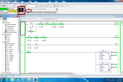
In that case, both the data files and program files are extended. Many PLCs have an online animation window, which shows current memory usage. It can be viewed either online or offline. This helps in better memory planning.

If you liked this article, then please subscribe to our YouTube Channel for Instrumentation, Electrical, PLC, and SCADA video tutorials.

You can also follow us on Facebook and Twitter to receive daily updates.

Read Next:

  • Sequential PLC Programming
  • S7-1500 S7-1200 S7-400 S7-300
  • HMI Screen Design Applications
  • Static and Temp Variables in PLC
  • Power Supply Sizing for Systems
Don't Miss Our Updates
Be the first to get exclusive content straight to your email.
We promise not to spam you. You can unsubscribe at any time.
Invalid email address
You've successfully subscribed !

Continue Reading

PLC Memory Mapping and I/O addressing
PLC Structured Text Program for Output Generation via Equations
Allen Bradley Powerflex VFD
Draw a Ladder Logic to switch ON-OFF a Bulb using a Toggle Switch ?
How to Convert an Electrical Diagram into PLC Program?
How to Convert Voltage to Current using Resistor ?
Share This Article
Facebook Whatsapp Whatsapp LinkedIn Copy Link
Share
Leave a Comment

Leave a Reply Cancel reply

Your email address will not be published. Required fields are marked *

Stay Connected

128.3kFollowersLike
69.1kFollowersFollow
210kSubscribersSubscribe
38kFollowersFollow

Categories

Explore More

How to do Scaling for Analog Input in RSLogix 500?
PLC based Automatic Packaging System
Allen Bradley PLC to PLC Communication in Studio 5000
How to Code a FIFO Queue in STL Language in Siemens PLC?
What is Nest Loading? – DCS and PLC Control Systems
PLC Programming for Pumping and Draining System
Machine Tool and Coolant Control: PLC Ladder Logic Design
PLC Level Control of Two Tanks

Keep Learning

Analog Input Card Resolution Effects on Accuracy

PLC Analog Input Card Resolution Effects on Accuracy

different PLC brands of Distributed IO

What is Distributed IO? – Decentralized Peripherals in PLC

Pulse Generation using Timer in Siemens PLC

Pulse Generation using Timer in Siemens PLC

intouch Basics

How to Create Project in Wonderware Intouch?

Types of Scan Time in a PLC

Programmable Logic Controller (PLC) Scan Time – Types, Theory

Pump and Mixer Operations Example PLC Timer-Based Control

Pump and Mixer Operations Example: PLC Timer-Based Control

User Defined Function Blocks in PLC

What are User Defined Function Blocks in PLC?

Downloading Free PLC software

Step by Step Guidelines for Downloading Free PLC software

Learn More

Control System Basic Wiring Practice Animation

PLC Connection between Instrument, Junction Box, Marshalling & System Cabinet

Gearbox within week Failing Journal Bearing upset Plant Operations

Gearbox within week Failing Journal Bearing upset Plant Operations

What is a Magnetic Field

Difference Between Electric Field and Magnetic Field

PLC Memory Organization - Data Files and Program Files

PLC Memory Organization – Data Files and Program Files

HART Transmitters Loop Checks

Loop Check of 4-20mA or HART Transmitters

Pressure and Temperature Compensation for Flow Transmitter

Why Pressure & Temperature Compensation required for Orifice Flow Meters ?

Resistance Temperature Detectors Troubleshooting Tips

Resistance Temperature Detectors Troubleshooting Tips

Hydrostatic level transmitter Formula

Hydrostatic Level Transmitter Questions

Menu

  • About
  • Privacy Policy
  • Copyright

Quick Links

  • Learn PLC
  • Helping Hand
  • Part Time Job

YouTube Subscribe

Follow US
All rights reserved. Reproduction in whole or in part without written permission is prohibited.
Welcome Back!

Sign in to your account

Username or Email Address
Password

Lost your password?