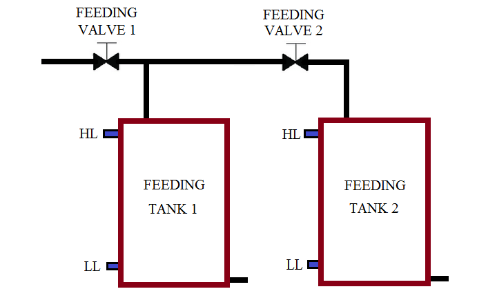
Write the PLC program for two tanks filling as per priority. Design the PLC Ladder Logic programming for this application.

In pneumatic conveying system two or more tanks are used for material supply. Sometimes it is necessary to define priority for tanks. For example, if there are two feeding tanks are used in system and both the tanks are empty so we which tank should be filled first?
So write priority logic in PLC for this problem. In this example we have taken two feeding tanks and we will fill tank as per priority. Hence we will fill tank 1 first if booth the tanks are detected empty.
Here we used normal logic for START/STOP cycle.lathing function is used here.
Priority selection logic is used in this network. If both the tanks are empty,priority for tank 1 will be activated.
If tank 2 is low , priority for tank 2 will be ON.
If tank 1 level is low and priority of tank 1 is ON, tank 1 feeding valve will be ON
If tank 2 is low and tank 1 priority is not activated, tank 2 feeding valve will be ON.
Note:-Above application may be different from actual application. We can also make this application by using other PLC also. This example is only for explanation purpose. This is the simple concept of priority for multiple tanks in conveying system; we can use this concept in other examples also.
All parameters and graphical representations considered in this example are for explanation purpose only, parameters or representation may be different in actual applications. Also all interlocks are not considered in the application.
If you liked this article, then please subscribe to our YouTube Channel for PLC and SCADA video tutorials.
You can also follow us on Facebook and Twitter to receive daily updates.
Read Next:
PLC Motor Operation based on Time
Traffic Light Control using PLC
PLC Automatic Control of Outputs
PLC Level Control of Two Tanks
This article explains how to blink lights in ladder logic with a detailed explanation video…
In this article, a simple example will teach you the conversion from Boolean algebra to…
In this article, you will learn the PLC cooking timer example for kitchen automation using…
Learn an example PLC program to control a pump based on level sensors using ladder…
In the PLC timer application for security camera recording, when motion is detected then camera…
In this example, we will learn batch mixing with PLC ladder logic program using timer…
View Comments
You have not mentioned the condition for high level