Inst ToolsInst ToolsInst Tools
  • Courses
  • Automation
    • PLC
    • Control System
    • Safety System
    • Communication
    • Fire & Gas System
  • Instrumentation
    • Design
    • Pressure
    • Temperature
    • Flow
    • Level
    • Vibration
    • Analyzer
    • Control Valve
    • Switch
    • Calibration
    • Erection & Commissioning
  • Interview
    • Instrumentation
    • Electrical
    • Electronics
    • Practical
  • Q&A
    • Instrumentation
    • Control System
    • Electrical
    • Electronics
    • Analog Electronics
    • Digital Electronics
    • Power Electronics
    • Microprocessor
  • Request
Search
  • Books
  • Software
  • Projects
  • Process
  • Tools
  • Basics
  • Formula
  • Power Plant
  • Root Cause Analysis
  • Electrical Basics
  • Animation
  • Standards
  • 4-20 mA Course
  • Siemens PLC Course
Reading: PLC Ladder Logic Example
Share
Notification Show More
Font ResizerAa
Inst ToolsInst Tools
Font ResizerAa
  • Courses
  • Design
  • PLC
  • Interview
  • Control System
Search
  • Courses
  • Automation
    • PLC
    • Control System
    • Safety System
    • Communication
    • Fire & Gas System
  • Instrumentation
    • Design
    • Pressure
    • Temperature
    • Flow
    • Level
    • Vibration
    • Analyzer
    • Control Valve
    • Switch
    • Calibration
    • Erection & Commissioning
  • Interview
    • Instrumentation
    • Electrical
    • Electronics
    • Practical
  • Q&A
    • Instrumentation
    • Control System
    • Electrical
    • Electronics
    • Analog Electronics
    • Digital Electronics
    • Power Electronics
    • Microprocessor
  • Request
Follow US
All rights reserved. Reproduction in whole or in part without written permission is prohibited.
Inst Tools > Blog > PLC Tutorials > PLC Ladder Logic Example

PLC Ladder Logic Example

PLC ladder Logic Example to understand relay control circuits into a virtual form where contacts and coils interact to perform control functions.

Last updated: November 2, 2023 3:32 pm
Editorial Staff
PLC Tutorials
6 Comments
Share
5 Min Read
SHARE

This topic is continuous to Relays in Ladder Logic Article. Click here to Read the Previous Article.

Contents
PLC Logic ExampleLadder-logic Program

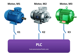
Here, we will emulate the exact same high-pressure alarm circuit using an Allen-Bradley MicroLogix 1000 PLC instead of a relay coil:

PLC Logic Example

PLC Ladder Logic Example

Ladder-logic Program

Ladder Logic Program

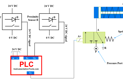
Suppose a fluid pressure of 36 PSI is applied to the pressure switch. This is less than the switch’s trip setting of 50 PSI, leaving the switch in its “normal” (closed) state. This sends power to input I:0/2 of the PLC.

The contact labeled I:0/2 drawn in the ladder-logic program of the PLC acts like a relay contact driven by a coil energized by input terminal I:0/2.

Thus, the closed pressure switch contact energizes input terminal I:0/2, which in turn “closes” the normally-open contact symbol I:0/2 drawn in the ladder-logic program.

This “virtual” contact sends virtual power to a virtual coil labeled B3:0/0, which is nothing more than a single bit of data in the PLC’s microprocessor memory.

“Energizing” this virtual coil has the effect of “actuating” any contact drawn in the program bearing the same label.

This means the normally-closed contact B3:0/0 will now be “actuated” and thus in the open state, not sending virtual power to the output coil O:0/1.

With virtual coil O:0/1 “unpowered,” the real-life output O:0/1 on the PLC will be electrically open, and the alarm lamp will be unpowered (off).

If we suppose a fluid pressure of 61 PSI be applied to the pressure switch, the normally-closed pressure switch contact will be actuated (forced) into the open state.

This will have the effect of de-energizing PLC input I:0/2, thus “opening” the normally-open virtual contact in the PLC program bearing the same label. This “open” virtual contact interrupts virtual power to the virtual coil B3:0/0, causing the normally-closed virtual contact B3:0/0 to “close,” sending virtual power to virtual coil O:0/1.

When this virtual output coil “energizes,” the real-life output channel of the PLC activates, sending real power to the alarm light to turn it on, signaling a high-pressure alarm condition.

We may simplify this PLC program further by eliminating the virtual control relay B3:0/0 and simply having input I:0/2 activate output O:0/1 through a “normally-closed” virtual contact:

Basic PLC program

The effect is the same: the PLC output O:0/1 will activate whenever input I:0/2 de-energizes (whenever the pressure switch is opened by a high pressure), turning on the alarm lamp in a high-pressure condition.

In a low-pressure condition, the energized input I:0/2 forces the virtual normally-closed contact I:0/2 to open, thus de-energizing the PLC’s output O:0/1 and turning the alarm lamp off.

Programmable Logic Controllers have not only greatly simplified the wiring of industrial logic controls by replacing multitudes of electromechanical relays with a microprocessor, but they have also added advanced capabilities such as counters, timers, sequencers, mathematical functions, communications, and of course the ability to easily modify the control logic through programming rather than by re-wiring relays.

The beauty of ladder-logic programming is that it translates the technician’s understanding of traditional relay control circuits into a virtual form where contacts and coils interact to perform practical control functions.

A key concept to master, however, is the association of real-life conditions to switch status based on the “normal” representation of those switch contacts, whether the switches be real (relay) or virtual (PLC). Once this vital concept is mastered, both hard-wired relay control circuits and PLC programs become possible to understand. Without mastering this vital concept, neither relay control circuits nor PLC programs may be understood.

If you liked this article, then please subscribe to our YouTube Channel for PLC and SCADA video tutorials.

You can also follow us on Facebook and Twitter to receive daily updates.

Read Next:

  • Contacts and Coils in PLC Ladder Logic
  • PLC Practice Questions
  • Mis-conceptions of PLC Ladder Logic
  • What is Ladder Diagram Programming?
  • PLC Sequencer Instruction with Example
Don't Miss Our Updates
Be the first to get exclusive content straight to your email.
We promise not to spam you. You can unsubscribe at any time.
Invalid email address
You've successfully subscribed !

Continue Reading

Dosing Pump PLC Logic
Difference between Compact PLC and Modular PLC
#13 PLC Best Practices – Disable Unused Communication Ports
Conveyor Speed Logic using Structured Text in PLC
Main differences between Sinking and Sourcing Circuits
PLC 1 Push Button to Turn ON or OFF 1 Output
Share This Article
Facebook Whatsapp Whatsapp LinkedIn Copy Link
Share
6 Comments
  • Bspreddy says:
    August 12, 2016 at 5:01 am

    Very useful

    Reply
  • Anoop says:
    August 13, 2016 at 2:05 am

    Thanks

    Reply
  • Anatolii says:
    October 15, 2016 at 5:48 pm

    many thanks

    Reply
  • Tayo Arogundade says:
    March 30, 2017 at 8:55 am

    Very kind of you,very good lecture.Thank so much. I am keen to learn more..
    Regards

    Reply
  • Raju Thakur says:
    June 2, 2019 at 12:01 pm

    Nice

    Reply
  • Usman says:
    August 16, 2019 at 12:13 pm

    Sir i need soft starter plc software

    Reply

Leave a Reply Cancel reply

Your email address will not be published. Required fields are marked *

Stay Connected

128.3kFollowersLike
69.1kFollowersFollow
210kSubscribersSubscribe
38kFollowersFollow

Categories

Explore More

Structured Text in PLC: Parking Information Systems
Studio 5000 Tutorial: PLC Programming for Digital Alarms
PLC Conveyor Motor Ladder Logic
Set the S5 Timer Value by a Memory Word
Create User-Defined Data Types and Function Blocks in Studio 5000
Siemens S7-300 CPU Suffix Explanation
PLC Pump Permissive Interlocks
Design Document for Project Systems Architecture

Keep Learning

Wiring in PLC System

Wiring in a PLC Control Panel

PLC Memory Mapping

PLC Memory Mapping and I/O addressing

Automatic Packing of Bottles

Automatic Packing of Bottles Programming

Programming in Omron PLC

Automatic Vacuum Cleaner Programming in Omron PLC

Control Loops

Control Loops Objective Questions and Answers

How CPU Execute Program in Siemens PLC?

How CPU Execute Program in Siemens PLC?

PLC Motor Logic with START, STOP, TEST Push buttons

PLC Motor Logic with START, STOP, TEST Push buttons

Programmable Logic Controller Quiz

Programmable Logic Controller Quiz

Learn More

Time Response Analysis

State Variable Analysis – Part I

Introduction to Mechatronics

Introduction to Mechatronics

Relay Motor Logic Circuit

Motor Control Circuits

Weighing Scale Maintenance

Preventive Maintenance of Weighing Scale

PLC Analog I/O Potential Problems

PLC Analog I/O Potential Problems – Troubleshooting & Issues

Loop Diagram

PT Loop Diagram Faults

Laser Cutting Precision and Accuracy

Benefits of Steel Laser Cutting

Magnetic Level Gauge Float

Magnetic Level Gauge Float Design

Menu

  • About
  • Privacy Policy
  • Copyright

Quick Links

  • Learn PLC
  • Helping Hand
  • Part Time Job

YouTube Subscribe

Follow US
All rights reserved. Reproduction in whole or in part without written permission is prohibited.
Welcome Back!

Sign in to your account

Username or Email Address
Password

Lost your password?