Inst ToolsInst ToolsInst Tools
  • Courses
  • Automation
    • PLC
    • Control System
    • Safety System
    • Communication
    • Fire & Gas System
  • Instrumentation
    • Design
    • Pressure
    • Temperature
    • Flow
    • Level
    • Vibration
    • Analyzer
    • Control Valve
    • Switch
    • Calibration
    • Erection & Commissioning
  • Interview
    • Instrumentation
    • Electrical
    • Electronics
    • Practical
  • Q&A
    • Instrumentation
    • Control System
    • Electrical
    • Electronics
    • Analog Electronics
    • Digital Electronics
    • Power Electronics
    • Microprocessor
  • Request
Search
  • Books
  • Software
  • Projects
  • Process
  • Tools
  • Basics
  • Formula
  • Power Plant
  • Root Cause Analysis
  • Electrical Basics
  • Animation
  • Standards
  • 4-20 mA Course
  • Siemens PLC Course
Reading: PLC Hoist Crane Programming: Example using Schneider
Share
Font ResizerAa
Inst ToolsInst Tools
Font ResizerAa
  • Courses
  • Design
  • PLC
  • Interview
  • Control System
Search
  • Courses
  • Automation
    • PLC
    • Control System
    • Safety System
    • Communication
    • Fire & Gas System
  • Instrumentation
    • Design
    • Pressure
    • Temperature
    • Flow
    • Level
    • Vibration
    • Analyzer
    • Control Valve
    • Switch
    • Calibration
    • Erection & Commissioning
  • Interview
    • Instrumentation
    • Electrical
    • Electronics
    • Practical
  • Q&A
    • Instrumentation
    • Control System
    • Electrical
    • Electronics
    • Analog Electronics
    • Digital Electronics
    • Power Electronics
    • Microprocessor
  • Request
Follow US
All rights reserved. Reproduction in whole or in part without written permission is prohibited.
Inst Tools > Blog > PLC Tutorials > PLC Hoist Crane Programming: Example using Schneider

PLC Hoist Crane Programming: Example using Schneider

Learn PLC hoist crane programming with a practical example using Schneider EcoStruxure Machine Expert to improve your automation skills.

Last updated: October 21, 2024 8:37 pm
Editorial Staff
PLC Tutorials
No Comments
Share
7 Min Read
SHARE

This article discusses the PLC program to control Crane movement using the Schneider PLC in the Ecostruxure Machine Expert-Basic software. The Crane Machine has a Trolley that can move Left or Right and a Hoist that can move Up or Down. This PLC system uses a Proximity Sensor to limit the range of Left or Right movement of the Trolley and Upward movement of the Hoist Crane. This system has an Emergency button to Stop all Crane movements without turning Off the system.

Contents
PLC Hoist Crane ProgrammingI/O AddressingSchneider Programming of PLC

PLC Hoist Crane Programming

This PLC program has 7 buttons:

  1. START SYSTEM (I0.0) button is used to turn ON the system.
  2. The STOP SYSTEM (I0.1) button is used to turn OFF the system.
  3. UP_BUTTON (I0.5) is used to move the Hoist Crane UP. When this button is Pressed, the Output OUT_UP (Q0.3) will be ON.
  4. DOWN_BUTTON (I0.4) button is used to move the Hoist Crane DOWN. When this button is Pressed, the output OUT_DOWN (Q0.2) will be ON.
  5. LEFT_BUTTON (I0.2) is used to move the Crane to the LEFT. When this button is Pressed, the output OUT_LEFT (Q0.0) will be ON.
  6. The RIGHT_BUTTON (I0.3) button is used to move the Crane to the RIGHT. When this button is Pressed, then the output OUT_RIGHT (Q0.1) will be ON.
  7. EMERGENCY (I0.6) button is used to Stop all Crane movement without turning OFF the system.

This Crane system uses a Proximity Sensor as a safety measure to prevent the Crane from moving beyond the safety limit.

  1. SENS_UP (I0.7) is used to limit the Highest position of the Hoist Crane, preventing the Hoist Crane from hitting the Hoist Motor.
  2. SENS_LEFT (I0.8) is used to limit the crane’s range when moving to the LEFT.
  3. SENS_RIGHT (I0.9) is used to limit the crane’s range when moving to the RIGHT.
Hoist Crane Automation with Schneider PLC
Crane PLC Programming

I/O Addressing

CommentInput (I)Output(Q)Memory Bits
START_SYSTEMI0.0  
STOP_SYSTEMI0.1  
LEFT_BUTTONI0.2  
RIGHT_BUTTONI0.3  
DOWN_BUTTONI0.4  
UP_BUTTONI0.5  
EMERGENCYI0.6  
SENS_LEFTI0.8  
SENS_RIGHTI0.9  
SENS_UPI0.7  
OUT_LEFT Q0.0 
OUT_RIGHT Q0.1 
OUT_DOWN Q0.2 
OUT_UP Q0.3 
SYSTEM_ON  M0
IR_LEFT  M1
IR_RIGHT  M2
IR_DOWN  M3
IR_UP  M4

Schneider Programming of PLC

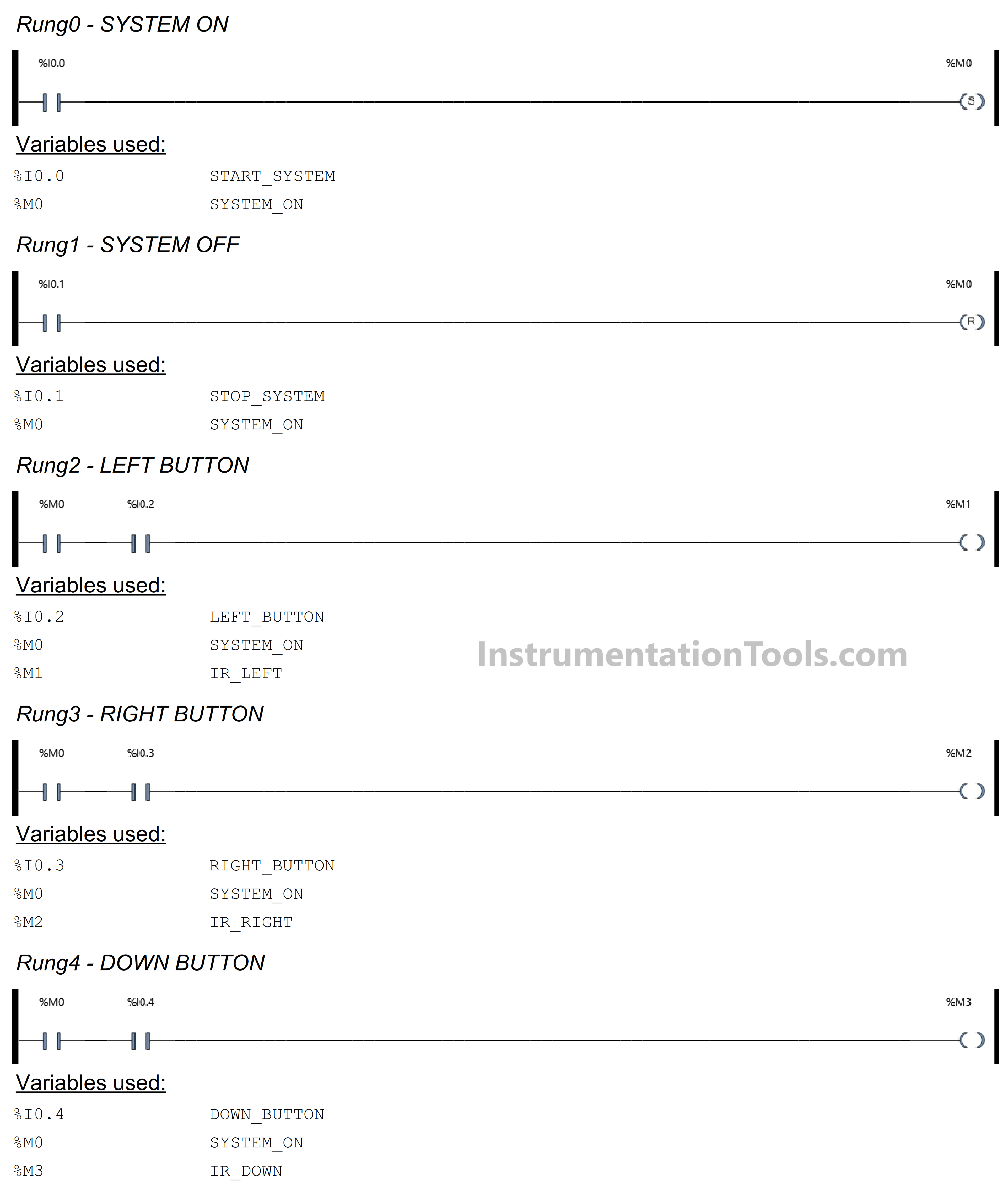
In this Rung, the memory bit SYSTEM_ON (M0) will be in the HIGH state if the START_SYSTEM (I0.0) button is Pressed. Because it uses the SET Coil Instruction, the memory bit SYSTEM_ON (M0) remains in the HIGH state even though the START_SYSTEM (I0.0) button has been Released.
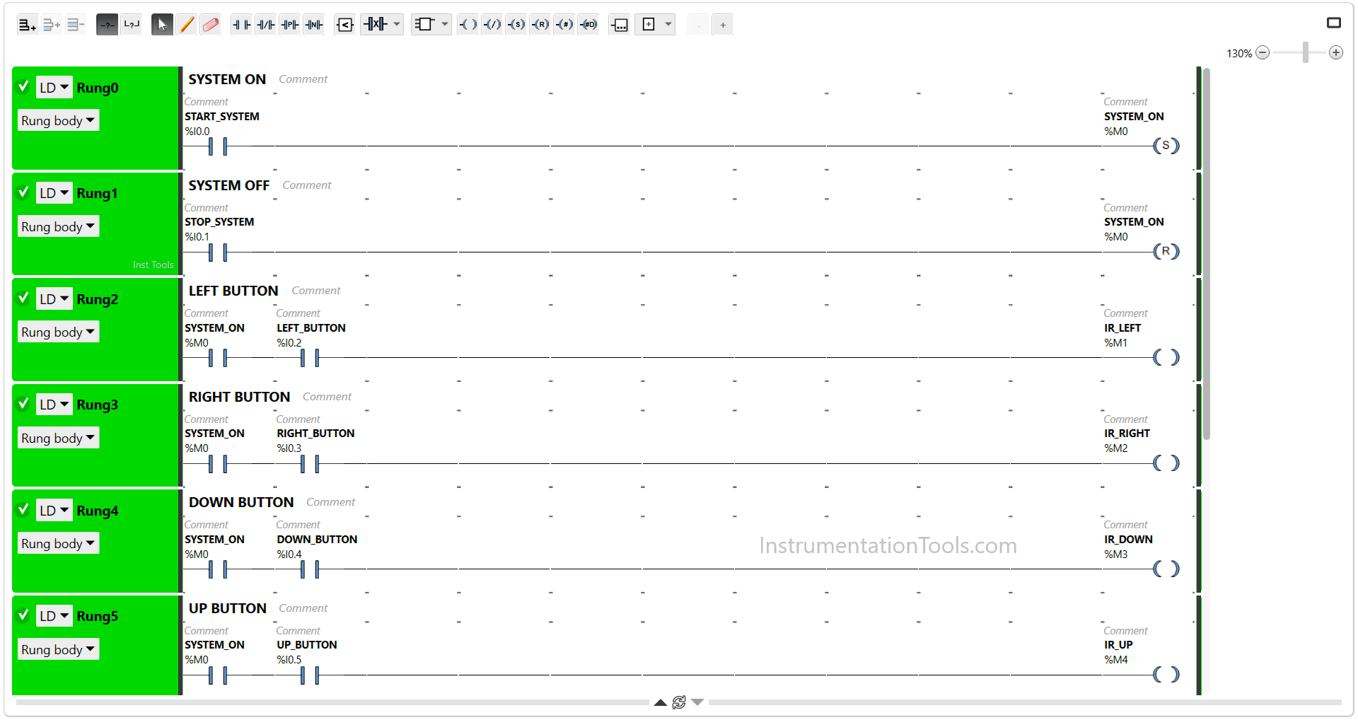
PLC Hoist Crane Programming

RUNG 1 (SYSTEM OFF)

In this Rung, the memory bit SYSTEM_ON (M0) will become LOW state if the STOP_SYSTEM (I0.1) button is Pressed. Because it uses the RESET Coil Instruction.

RUNG 2 (LEFT BUTTON)

In this Rung, the memory bit IR_LEFT (M1) will be in the HIGH state if the NO contact of memory bit SYSTEM_ON (M0) in the HIGH state and the LEFT_BUTTON (I0.2) button is Pressed.

RUNG 3 (RIGHT BUTTON)

In this Rung, the memory bit IR_RIGHT (M2) will be in the HIGH state if the NO contact of memory bit SYSTEM_ON (M0) in the HIGH state and the RIGHT_BUTTON (I0.3) button is Pressed.

RUNG 4 (DOWN BUTTON)

In this Rung, the memory bit IR_DOWN (M3) will be in the HIGH state if the NO contact of memory bit SYSTEM_ON (M0) in the HIGH state and the DOWN_BUTTON (I0.4) button is Pressed.
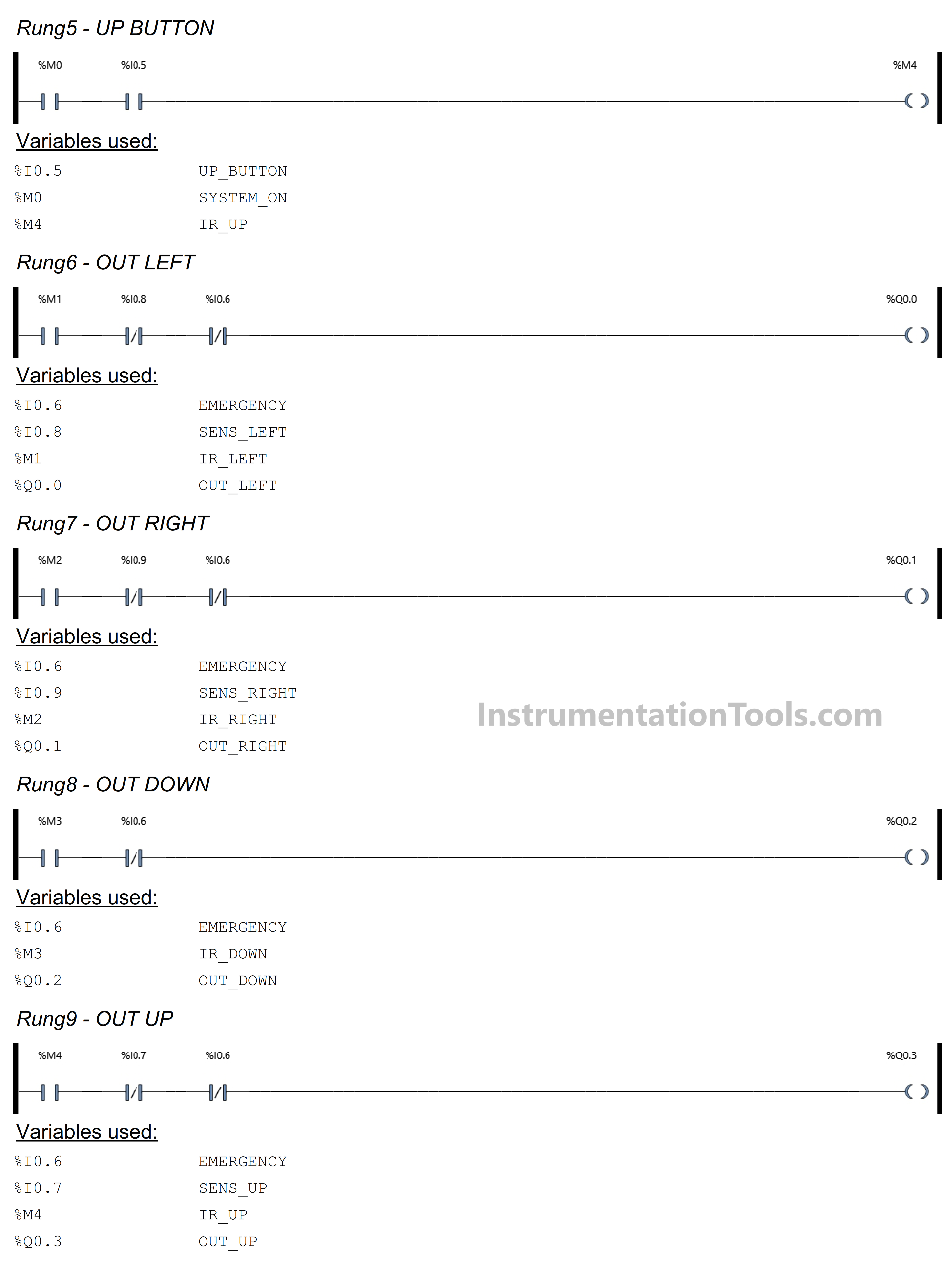
RUNG 5 (UP BUTTON)

In this Rung, the memory bit IR_UP (M4) will be in the HIGH state if the NO contact of memory bit SYSTEM_ON (M0) in the HIGH state and the UP_BUTTON (I0.5) button is Pressed.
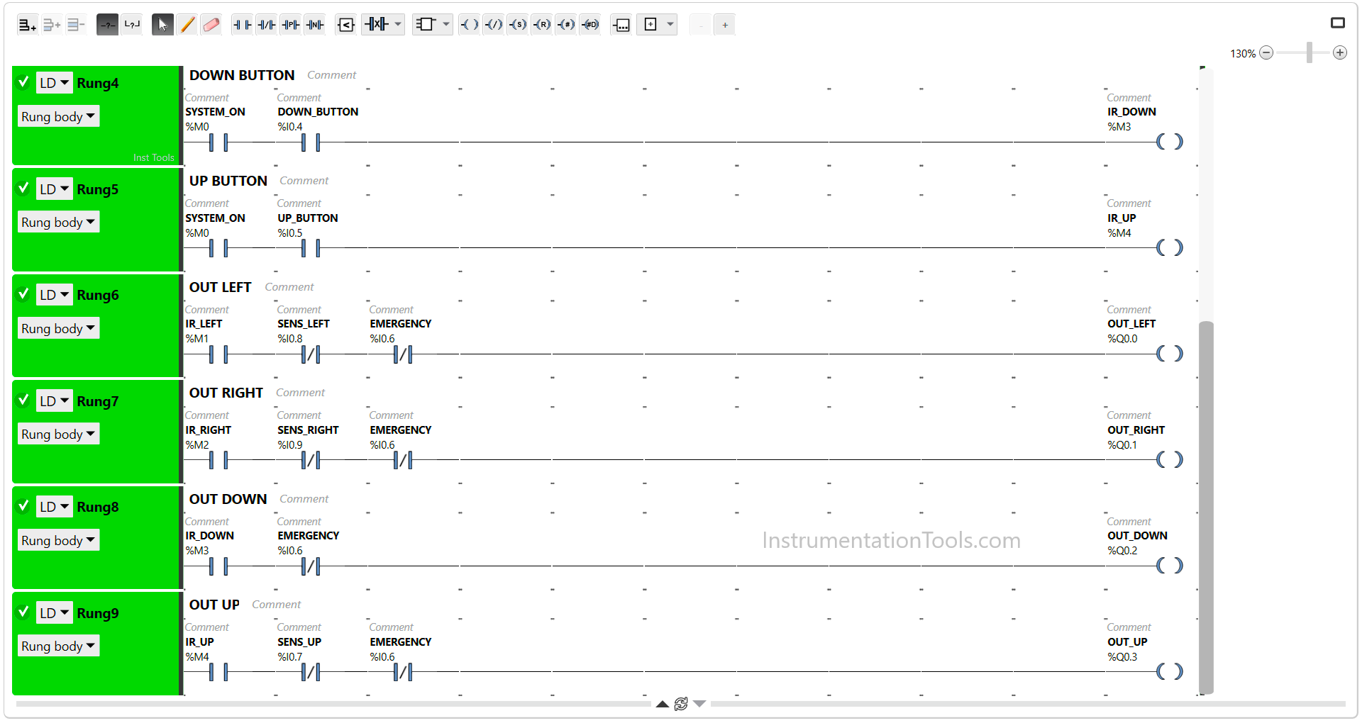
Example using Schneider PLC

RUNG 6 (OUT LEFT)

In this Rung, when the NO contact of memory bit IR_LEFT (M1) in the HIGH state, the Output OUT_LEFT (Q0.0) will be ON.

The OUT_LEFT (Q0.0) output will be OFF if the EMERGENCY (I0.6) button is Pressed or if the NC contact of Proximity Sensor SENS_LEFT (I0.8) in the HIGH state.

RUNG 7 (OUT RIGHT)

In this Rung, when the NO contact of memory bit IR_RIGHT (M2) in the HIGH state, the Output OUT_RIGHT (Q0.1) will be ON.

The OUT_RIGHT (Q0.1) output will be OFF if the EMERGENCY (I0.6) button is Pressed or if the NC contact of Proximity Sensor SENS_RIGHT (I0.9) in the HIGH state.

RUNG 8 (OUT DOWN)

In this Rung, when the memory bit IR_DOWN (M3) in the HIGH state, the Output OUT_DOWN (Q0.2) will be ON.

The OUT_DOWN (Q0.2) output will be OFF if the EMERGENCY (I0.6) button is Pressed.

RUNG 9 (OUT UP)

In this Rung, when the NO contact of memory bit IR_UP (M4) in the HIGH state, the Output OUT_UP (Q0.3) will be ON.

The OUT_UP (Q0.3) output will be OFF if the EMERGENCY (I0.6) button is Pressed or if the NC contact of Proximity Sensor SENS_UP (I0.7) in the HIGH state.

Read Next:

  • Conveyor Sorting with Color Detection
  • Difference Between PLC and CNC Machine
  • PLC Programming Clothes Washing System
  • PLC Example for Traffic Light FBD Program
  • PLC Program for Password Management
Don't Miss Our Updates
Be the first to get exclusive content straight to your email.
We promise not to spam you. You can unsubscribe at any time.
Invalid email address
You've successfully subscribed !

Continue Reading

Feedback Monitoring in Safety PLC
Draw a Ladder Logic to switch ON-OFF a Bulb using a Toggle Switch ?
PLC SCL Program for Marking Machine
SFC Language in PLC Programming
Scaling with Parameters (SCP) Instruction in PLC
Difference Between PLC and SCADA
Share This Article
Facebook Whatsapp Whatsapp LinkedIn Copy Link
Share
Leave a Comment

Leave a Reply Cancel reply

Your email address will not be published. Required fields are marked *

Stay Connected

128.3kFollowersLike
69.1kFollowersFollow
210kSubscribersSubscribe
38kFollowersFollow

Categories

Explore More

Implement UDT in PLC Programming: User-Defined Data Type
Steps to Configure TCP/IP Communication in Siemens S7-1200 PLC
Understanding Braking Theory in VFD
Applications of PLC Programming in Bottle Filling Process
What are Faceplates? How to Create a Faceplate? HMI Visualization
How to Communicate with Excel from Intouch SCADA?
Difference Between Industrial Computer (IPC) and Normal Computer (PC)
Motor Control Circuits

Keep Learning

Causes of PLC Stop Mode

Various Causes for PLC Going in Stop Mode

100 PLC Quiz Questions

100 PLC Quiz Questions : True or False

PLC Program to Operate Stamping of Parts

PLC Application for Stamping Operation – Example Programming

AI AO DI DO Questions

AI, AO, DI, DO Questions (PLC I/O Types)

FactoryTalk View Studio Site Edition Pop-Up Confirm Action

How to Automatically Close Pop-up in FactoryTalk View Studio?

Sequential Timer Control of Lamps

Schneider PLC Example: Control Lamps Sequences

PLC Data Logging and Transmission

Moving Data between PLCs – Siemens Basics – TSEND TRCV

PLC Program for Daily Production Record

PLC Program for Daily Production Record

Learn More

Introduction to Fieldbus Function Blocks

Synchronous Motor Principle

Synchronous Motors

Top PLC Manufacturers

Top PLC Manufacturers

Hook-up Diagram for Pressure Gauge

What is Instrument Hook Up Diagram ?

foundation-fieldbus-vs-profibus

Comparison between Foundation Fieldbus and Profibus

Ball Valve Material Selection

Ball Valve Material Selection

Introduction to SCADA

SCADA Graphics

What is SCADA ? How does SCADA Works ?

Menu

  • About
  • Privacy Policy
  • Copyright

Quick Links

  • Learn PLC
  • Helping Hand
  • Part Time Job

YouTube Subscribe

Follow US
All rights reserved. Reproduction in whole or in part without written permission is prohibited.
Welcome Back!

Sign in to your account

Username or Email Address
Password

Lost your password?