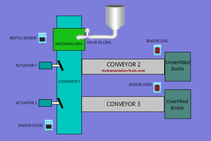
This article discusses the PLC controlled conveyor and weighing with labeling automation using the XG-5000 PLC software. This system has a Conveyor to carry the product and a Weighing Indicator to weigh the product. When a product is detected, the Conveyor will stop for a moment to weigh the product. If the product weight matches the standard (Set value), the Piston will active to attach the label. If the product weight does not meatches the Standard (Set value), the Piston will not active and the alarm will turn On. Products that have received a label will be counted. The alarm will turn On when the product quantity has reached the maximum limit.
PLC Controlled Conveyor and Weighing
Buttons, Sensor, and Limit Switch used are listed below:
- The PB_START (P00000) button is used to turn On the system.
- The PB_STOP (P00001) button is used to turn Off the system.
- The RESET_COUNTER (P00004) button is used to reset the counter data.
- The SENS_PRODUCT (P00002) sensor is used to detect the product.
- Limit Switch LS_PISTON (P00003) is used as a Piston Interlock.
The CONVEYOR (P00043) output will be ON when the PB_START (P00000) button is Pressed.
When the SENS_PRODUCT (P00002) sensor detects the product, the CONVEYOR (P00043) Output will Stop for 2 seconds to weigh the product.
If the weight of the product in memory word PV_WEIGHING (D00010) is Equal to “Set value” that has been Set in memory word SV_WEIGHING (D00011), then the Output LABELLING_PISTON (P00041) will be ON to attach the Label to the Product.
If within 3 seconds the weight of the product in the memory word PV_WEIGHING (D00010) is Not Equal to “Set value” in the memory word SV_WEIGHING (D00011), then the ALARM Output (P00042) will be ON.
Products that have received a label will be counted in the memory word PV_COUNTER (D00000). The quantity of Products counted has a maximum limit that can be Set in the memory word SV_COUNTER (D00001).
When the quantity of products reaches the maximum limit, the ALARM (P00042) Output will be ON.
The value in the memory word PV_COUNTER (D00000) will be Reset to zero “0” when the RESET_COUNTER (P00004) button is Pressed.
Project Addresses
| Comment | Input (I) | Output(Q) | Memory Word | Memory Bits | Timer |
| PB_START | P00000 | ||||
| PB_STOP | P00001 | ||||
| SENS_PRODUCT | P00002 | ||||
| LS_PISTON | P00003 | ||||
| RESET_COUNTER | P00004 | ||||
| LABELLING_PISTON | P00041 | ||||
| ALARM | P00042 | ||||
| CONVEYOR | P00043 | ||||
| TIMER1 | T0000 | ||||
| TIMER2 | T0001 | ||||
| PV_COUNTER | D00000 | ||||
| SV_COUNTER | D00001 | ||||
| PV_WEIGHING | D00010 | ||||
| SV_WEIGHING | D00011 | ||||
| SYSTEM_ON | M00000 | ||||
| STOP_CONVEYOR | M00001 |
Programming of PLC
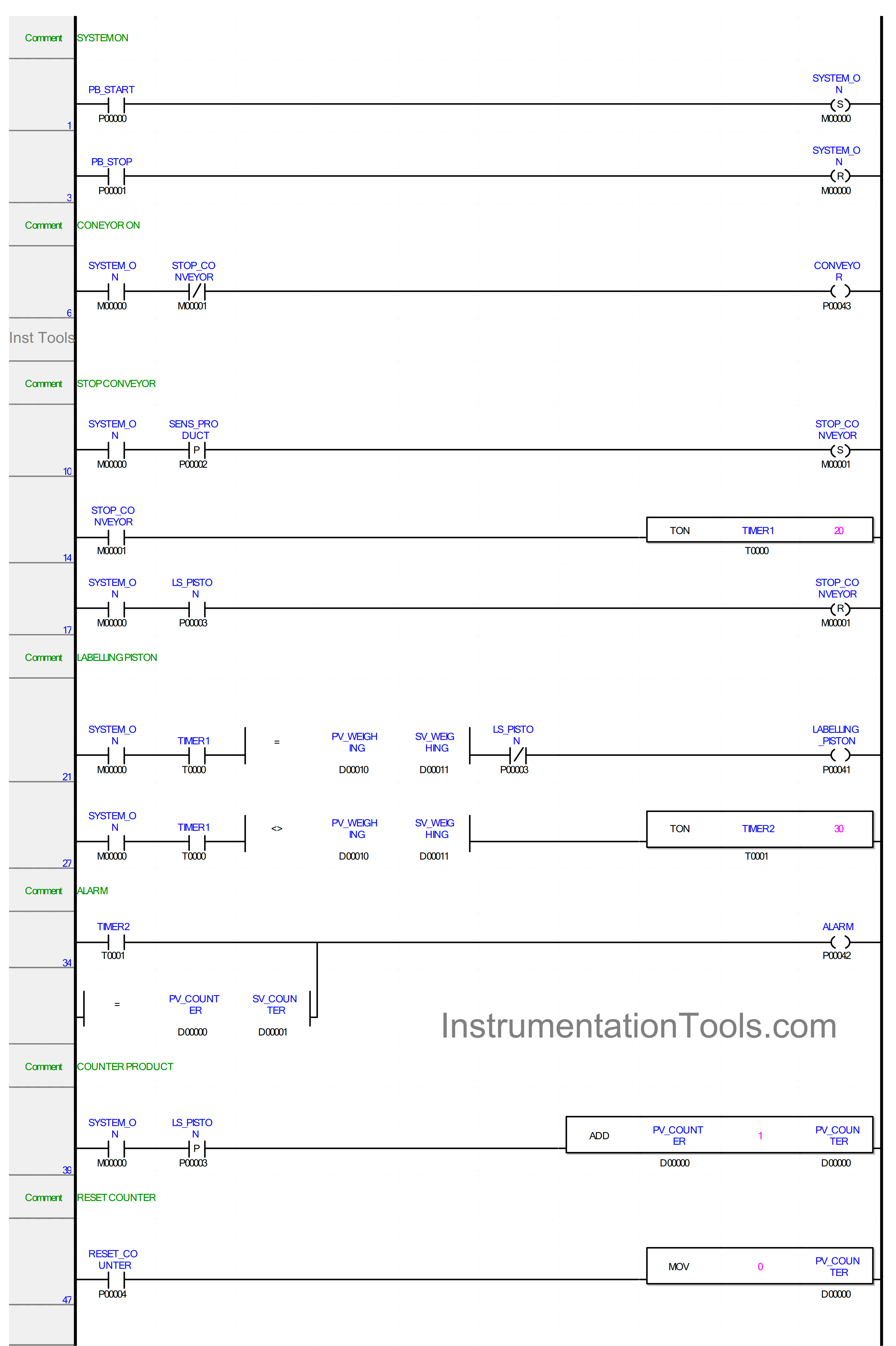
RUNG 1
In this Rung, when the PB_START (P00000) button is Pressed, the memory bit SYSTEM_ON (M00000) changes to HIGH state. The memory bit SYSTEM_ON (M00000) remains in the HIGH state even though the PB_START (P00000) button has been Released because it uses the SET Coil instruction.
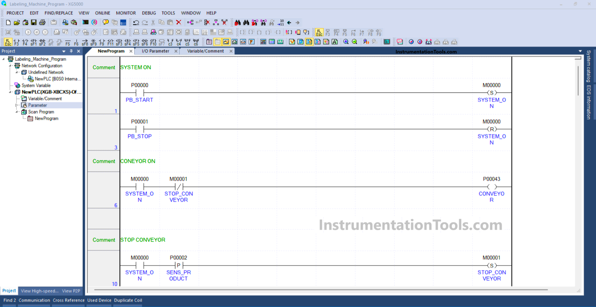
RUNG 3
In this Rung, the memory bit SYSTEM_ON (M00000) will change to the LOW state if the PB_STOP (P00001) button is Pressed because it uses the RESET Coil instruction.
RUNG 6
When the NO contact of memory bit SYSTEM_ON (M00000) is in the HIGH state, the CONVEYOR (P00043) Output will be ON.
If the NO contact of memory bit SYSTEM_ON (M00000) in the LOW state or the NC contact of memory bit STOP_CONVEYOR (M00001) in the HIGH state, then the CONVEYOR (P00043) Output will be OFF.
RUNG 10
In this Rung, if the NO contacts of memory bit SYSTEM_ON (M00000) and the Sensor SENS_PRODUCT (P00002) are in the HIGH state, then the memory bit STOP_CONVEYOR (M00001) will be in the HIGH state.
Because it uses the SET Coil Instruction, the memory bit STOP_CONVEYOR (M00001) will remain in the HIGH state even though the SENS_PRODUCT (P00002) Sensor has changed to the LOW state.
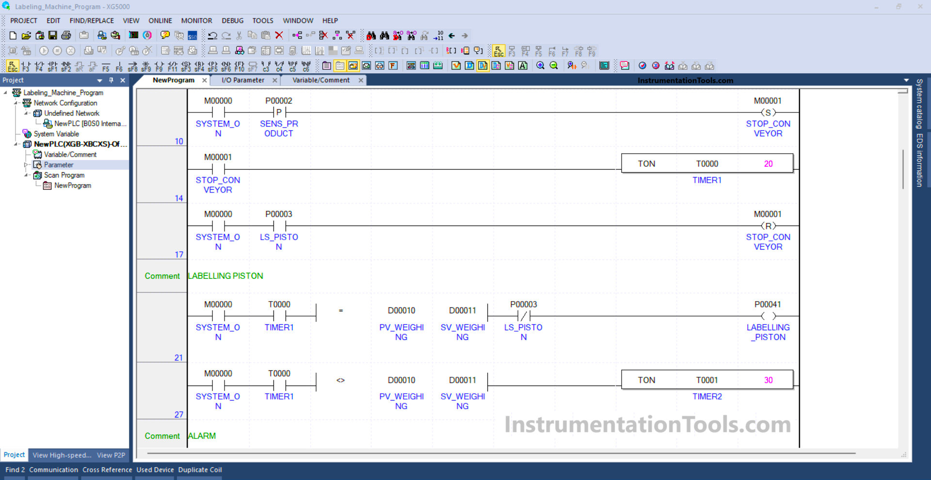
RUNG 14
In this Rung, Timer TIMER1 (T0000) will Start counting up to 2 seconds when the NO contact of memory bit STOP_CONVEYOR (M00001) is in the HIGH state.
RUNG 17
In this Rung, the memory bit STOP_CONVEYOR (M00001) will change to the LOW state when the NO contact of Limit Switch LS_PISTON (P00003) is in the HIGH state. Because it uses the RESET Coil Instruction.
RUNG 21
When the NO contacts of memory bit SYSTEM_ON (M00000) and TIMER1 (T0000) are in the HIGH state and the value in memory word PV_WEIGHING (D00010) is Equal to SV_WEIGHING (D00011), then the Output LABELLING_PISTON (P00041) will be ON.
The LABELLING_PISTON (P00041) output will be OFF when the NC contact of Limit Switch LS_PISTON (P00003) is in the HIGH state.
RUNG 27
In this rung, Timer TIMER2 (T0001) will Start counting up to 3 seconds when the NO contacts of memory bit SYSTEM_ON (M00000) and TIMER1 (T0000) are in the HIGH state and the value in memory word PV_WEIGHING (D00010) is not Equal to SV_WEIGHING (D00011).
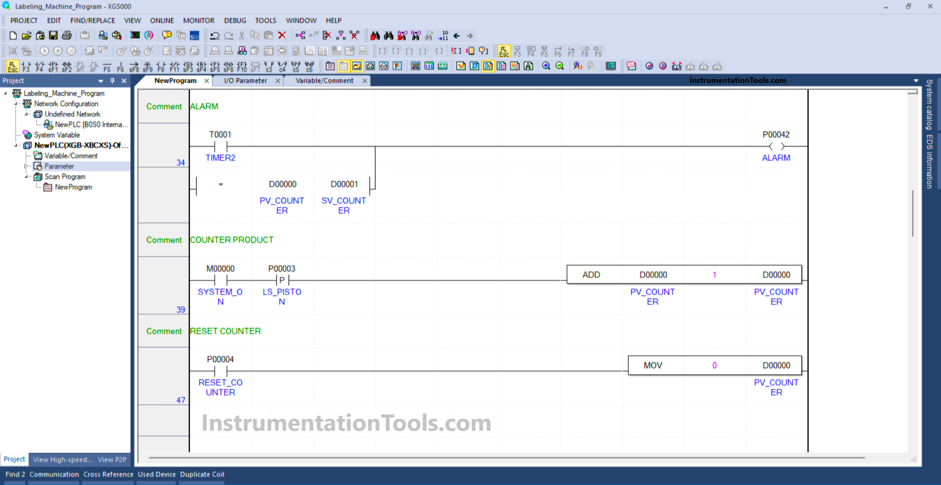
RUNG 34
In this Rung, the ALARM (P00042) output will be ON if the contact NO of Timer TIMER2 (T0001) in the HIGH state or the value in memory word PV_COUNTER (D00000) is Equal to SV_COUNTER (D00001).
RUNG 39
In this Rung, the value in memory word PV_COUNTER (D00000) will increase (+1) if the NO the contact of memory bit SYSTEM_ON (M00000) and the Limit Switch LS_PISTON (P00003) are in the HIGH state.
RUNG 47
When the RESET_COUNTER (P00004) button is Pressed, the value in memory word PV_COUNTER (D00000) will be Reset to zero “0”.
Because the MOV instruction moves the zero value “0” to the memory word PV_COUNTER (D00000).
Read Next:
- PLC Logic for Star-Delta System using 1 Button
- Highway Lights Program using RTC in Omron PLC
- PLC Structured Text Program for Marking Machine
- Automate Batch Mixing with Repeated Cycles in PLC
- PLC Program for Multi-Color Sorting Conveyor System