This article discusses an automatic sand sieving system using PLC control logic. The system is designed to separate sand from other materials using a sieve. It is capable of measuring the weight of the sand and setting the duration of the sieving process. The system will trigger an indicator alarm once the process is completed.
Program Objective
System Operational Steps:
- Initial Parameter Setup:
The system can only be operated after the sieving time and sand weight parameters have been set. - Sand Weighing:
The system will automatically weigh the sand according to the specified weight using a sliding valve and weighing indicator. - Motor and Sieve Activation:
Once the desired sand weight is reached, the motor will start to operate the sieve. - Sieving Process:
The sieve will run for the specified duration. The sieved sand will fall into a collection bin. - Opening of Output Sliding Valve:
After the sieving process is complete, the output sliding valve will open to begin the disposal of residual material. - Residual Material Disposal:
The gate on the sieve will open simultaneously with the output sliding valve to release any remaining material inside the sieve. Both the gate and the output sliding valve will close again once the sand weight on the scale drops below 5 kg. - Alarm:
An alarm will be activated to indicate that the sieving process is complete. The alarm will remain on until the system is stopped manually.
Sand Sieve System
Mapping Details
| S.No. | Comment | Input (I) | Output(Q) | Memory Bit | Memory Word | Timers |
|---|---|---|---|---|---|---|
| 1 | START | 0.00 | ||||
| 2 | STOP | 0.01 | ||||
| 3 | SLIDING_VALVE_IN | 100.00 | ||||
| 4 | MOTOR_SIEVE | 100.01 | ||||
| 5 | SLIDING_VALVE_OUT | 100.02 | ||||
| 6 | GATE_SIEVE_OUT | 100.03 | ||||
| 7 | ALARM | 100.04 | ||||
| 8 | SV_WEIGHT | D0 | ||||
| 9 | SV_TIME | D2 | ||||
| 10 | PV_WEIGHT | D4 | ||||
| 11 | TIMER_SIEVE | T000 | ||||
| 12 | SYSTEM_ON | W0.00 | ||||
| 13 | ILC_WEIGHT | W0.01 |
PLC Control Logic
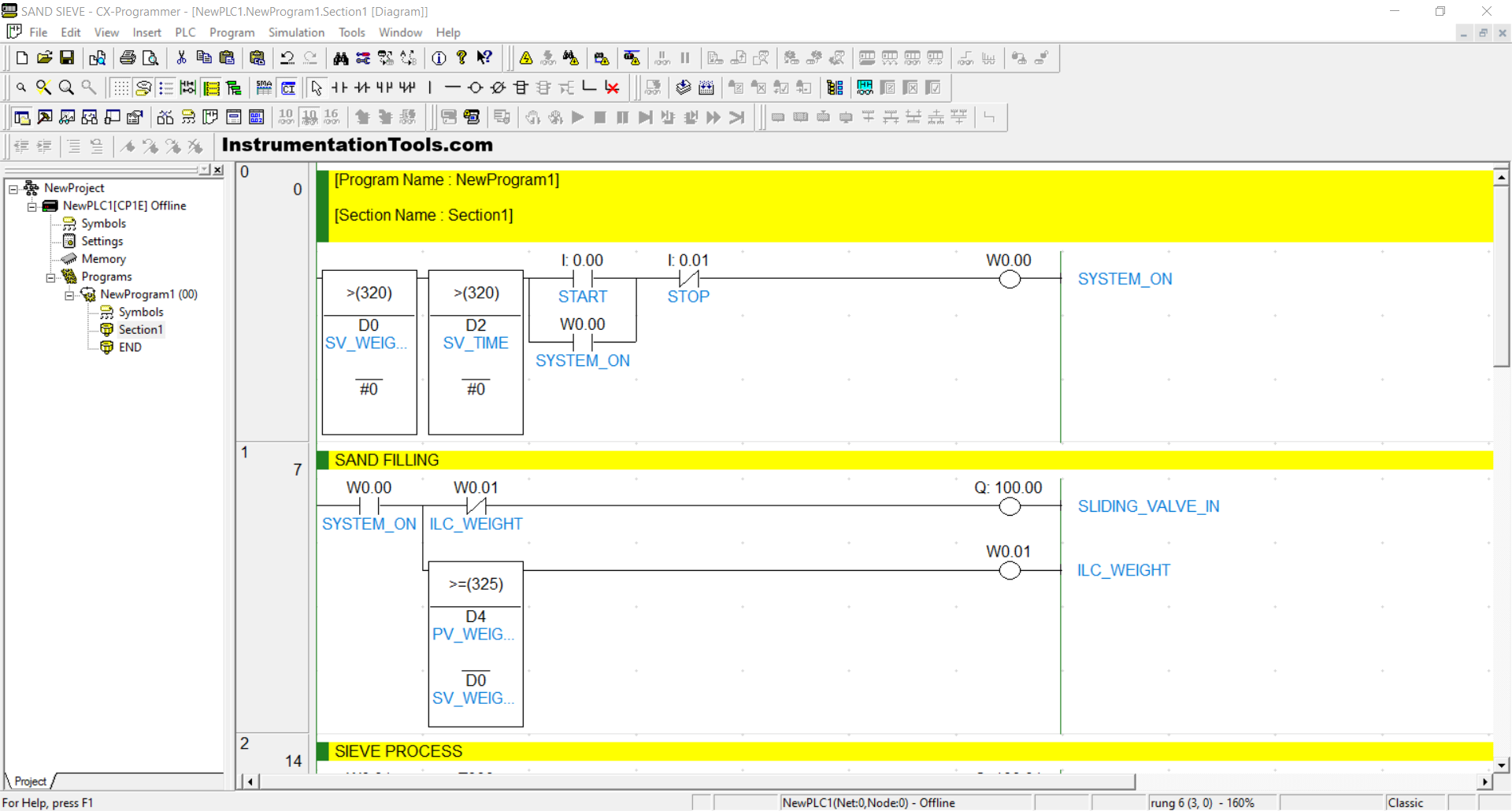
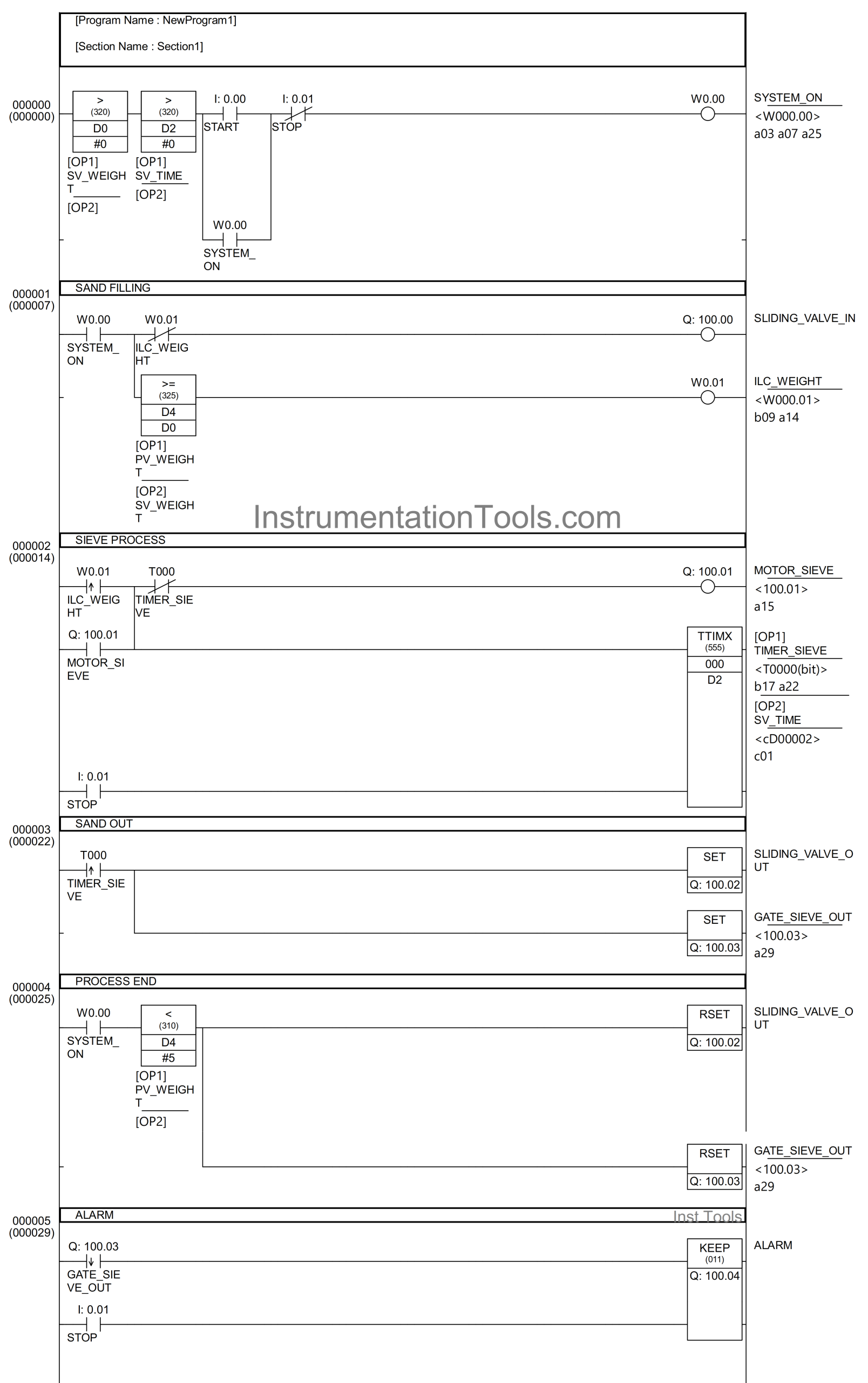
RUNG 0 (START SYSTEM)
In this Rung, if the START (0.00) button is pressed and the value in the memory words SV_WEIGHT (D0) and SV_TIME (D2) is greater than zero “0”, then the memory bit SYSTEM_ON (W0.00) will be in the HIGH state. Because it uses Latching, the memory bit SYSTEM_ON (W0.00) will remain in the HIGH state even though the START(0.00) button has been released.
The memory bit SYSTEM_ON (W0.00) will be in the LOW state if the STOP (0.01) button is pressed.
RUNG 1 (SAND FILLING)
In this Rung, if the NO contact of the memory bit SYSTEM_ON (W0.00) is in the HIGH state, then the SLIDING_VALVE_IN (100.00) output will be OPEN.
When the value in the memory word PV_WEIGHT(D4) is greater than or equal to SV_WEIGHT (D0), the memory bit ILC_WEIGHT (W0.01) will be in the HIGH state, and the SLIDING_VALVE_IN (100.00) output will be CLOSED due to the Interlock.
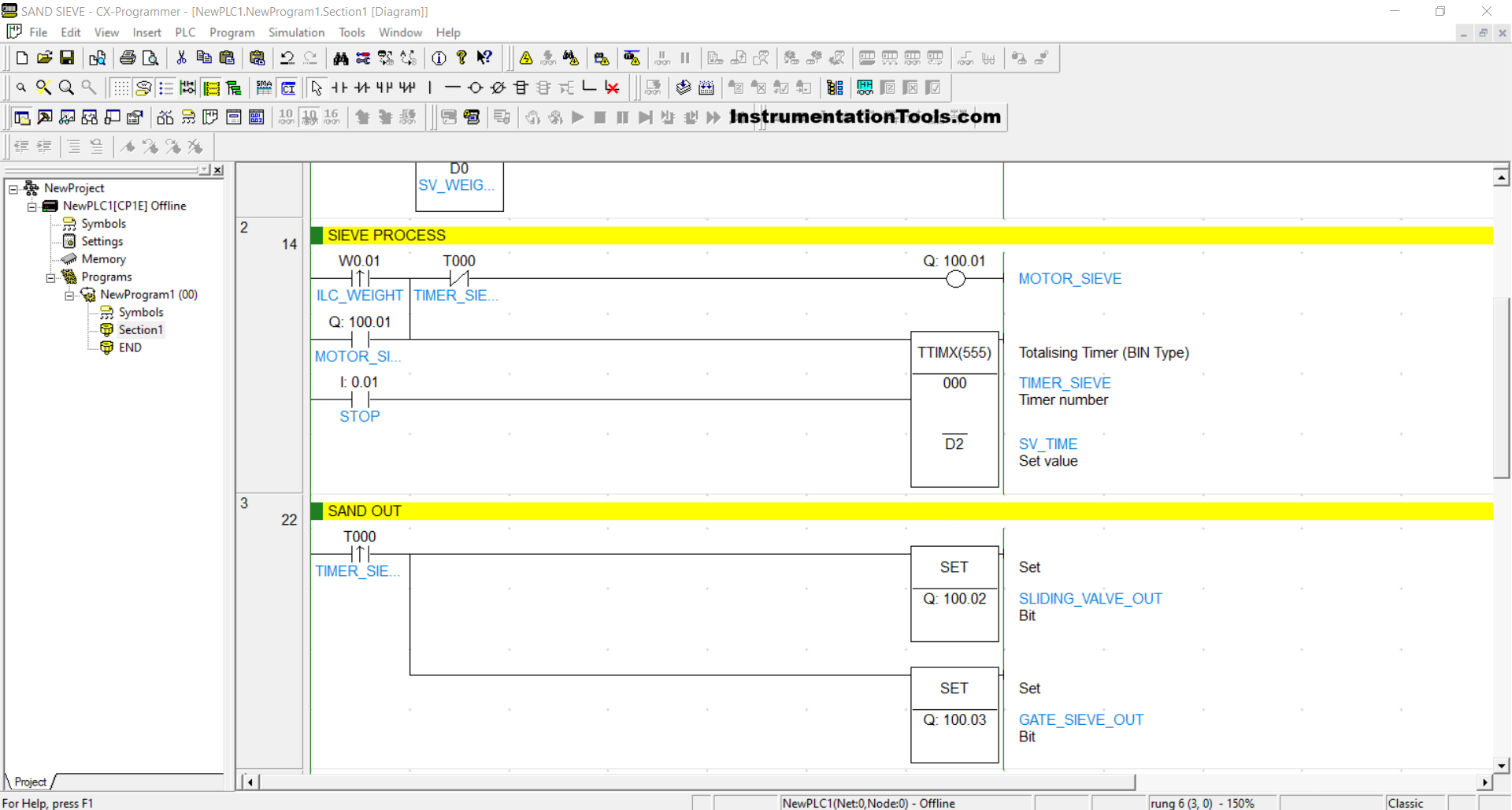
RUNG 2 (SIEVE PROCESS)
In this Rung, if the NO contact of the memory bit ILC_WEIGHT (W0.01) is in the HIGH state, then the MOTOR_SIEVE (100.01) output will be ON. Because it uses Latching, the MOTOR_SIEVE (100.01) output will remain ON even though the memory bit ILC_WEIGHT (W0.01) is in the LOW state.
The timer TIMER_SIEVE (T000) will start counting, and after it has finished counting, the MOTOR_SIEVE (100.01) output will be OFF due to the interlock.
RUNG 3 (SAND OUT)
When the NO contact of the TIMER_SIEVE (T000) timer is in the HIGH state, then the SLIDING_VALVE_OUT (100.02) and GATE_SIEVE_OUT (100.03) outputs will be OPEN.
Because it uses the SET instruction, the outputs SLIDING_VALVE_OUT (100.02) and GATE_SIEVE_OUT (100.03) will remain OPEN even though the NO contact of the TIMER_SIEVE (T000) timer is in the LOW state.
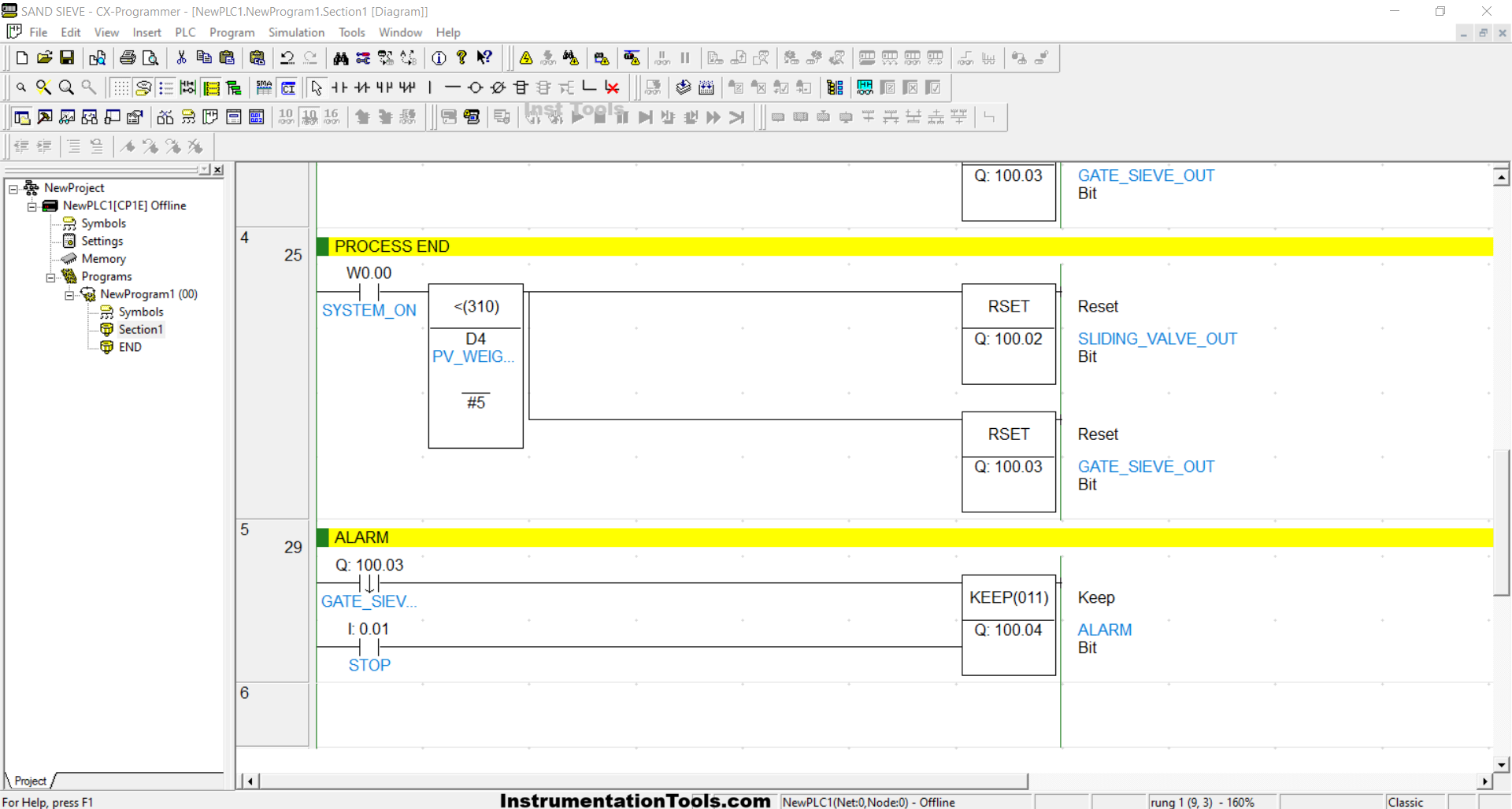
RUNG 4 (PROCESS END)
In this Rung, when the NO contact of the memory bit SYSTEM_ON (W0.00) is in the HIGH state and the value of the memory word PV_WEIGHT (D4) is less than “5”, the SLIDING_VALVE_OUT (100.02) and GATE_SIEVE_OUT (100.03) outputs will be CLOSED because of the RSET instruction.
RUNG 5 (ALARM)
When the NO contact of GATE_SIEVE_OUT (100.03) is in the HIGH state, the ALARM (100.04) output will be ON and will only be OFF if the STOP (0.01) button is pressed.
Read Next:
- PLC Logic for Continuous Filling Operation
- Difference Between FC and FB in Tia Portal
- LOGO PLC Full Programming Course Download
- Baking with Auto and Manual Modes PLC Logic
- Mitsubishi FX3U PLC with Weinview MT6071iE HMI


