Inst ToolsInst ToolsInst Tools
  • Courses
  • Automation
    • PLC
    • Control System
    • Safety System
    • Communication
    • Fire & Gas System
  • Instrumentation
    • Design
    • Pressure
    • Temperature
    • Flow
    • Level
    • Vibration
    • Analyzer
    • Control Valve
    • Switch
    • Calibration
    • Erection & Commissioning
  • Interview
    • Instrumentation
    • Electrical
    • Electronics
    • Practical
  • Q&A
    • Instrumentation
    • Control System
    • Electrical
    • Electronics
    • Analog Electronics
    • Digital Electronics
    • Power Electronics
    • Microprocessor
  • Request
Search
  • Books
  • Software
  • Projects
  • Process
  • Tools
  • Basics
  • Formula
  • Power Plant
  • Root Cause Analysis
  • Electrical Basics
  • Animation
  • Standards
  • 4-20 mA Course
  • Siemens PLC Course
Reading: #20 PLC Best Practices – Identify Critical Alerts
Share
Font ResizerAa
Inst ToolsInst Tools
Font ResizerAa
  • Courses
  • Design
  • PLC
  • Interview
  • Control System
Search
  • Courses
  • Automation
    • PLC
    • Control System
    • Safety System
    • Communication
    • Fire & Gas System
  • Instrumentation
    • Design
    • Pressure
    • Temperature
    • Flow
    • Level
    • Vibration
    • Analyzer
    • Control Valve
    • Switch
    • Calibration
    • Erection & Commissioning
  • Interview
    • Instrumentation
    • Electrical
    • Electronics
    • Practical
  • Q&A
    • Instrumentation
    • Control System
    • Electrical
    • Electronics
    • Analog Electronics
    • Digital Electronics
    • Power Electronics
    • Microprocessor
  • Request
Follow US
All rights reserved. Reproduction in whole or in part without written permission is prohibited.
Inst Tools > Blog > PLC Tutorials > #20 PLC Best Practices – Identify Critical Alerts

#20 PLC Best Practices – Identify Critical Alerts

Identify PLC critical alerts and program a trap to monitor the trigger conditions and the alert state for any deviation.

Last updated: September 23, 2021 12:03 pm
Editorial Staff
PLC Tutorials
No Comments
Share
3 Min Read
SHARE

Identify critical alerts and program a trap for those alerts. Set the trap to monitor the trigger conditions and the alert state for any deviation.

Contents
Identify PLC Critical AlertsExample 1Example 2Example 3
Security ObjectiveTarget Group
MonitoringIntegration / Maintenance Service Provider

Identify PLC Critical Alerts

In most cases, alert-states are boolean (True, False) and triggered by certain conditions as displayed below.

For example, the trigger bit for the alert ‘overpressure’ becomes TRUE, if Condition 1 ‘pressure switch 1’, Condition 2 ‘pressure sensor value over critical threshold’, through n., are TRUE.
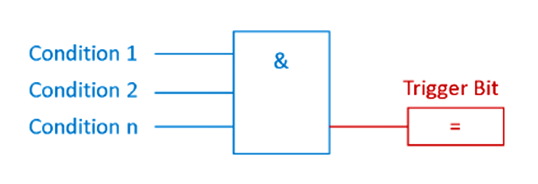
alert-states in PLC

To masquerade an attack, an adversary could suppress the alert trigger bit and cause a false negative.

A trap for false negatives monitors the conditions for the trigger bit and the negated trigger bit itself. With this simple setup, a false negative is detected. See the following picture:

False Negative Logic in PLC

In other cases, an adversary could deliberately cause false positives, to wear down the process operator’s attention.

In the same manner of the false negative trap, false positives can also be detected by monitoring the alert trigger bit and if the trigger conditions are met. If the conditions are NOT met, but the trigger bit is active, a false positive is detected: See the following picture:
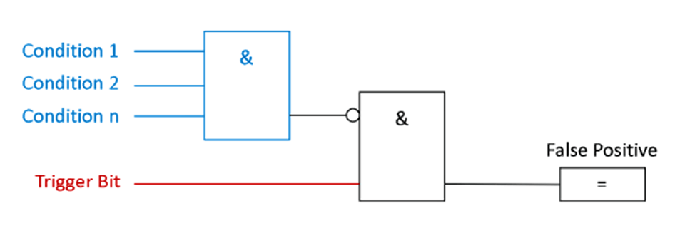
False Positive PLC Logic

Example 1

Siemens offers in their Siemens S7-1200/1500 Products a Webserver with a wide range of functions, for example, display of the PLC-State, cycle time, or scope records.

It also has the option to view and modify data tables and variables. The access rights to the Webserver can be modified in the PLC-Hardware Settings.

In case of mis-configured access rights, an adversary could gain access to the PLC Variables and Datablocks. To create a false positive, the adversary selects an alert trigger bit and alters the state.

Example 2

In the Triton/Trisys/HatMan attack, rogue code suppressed alert states.

Example 3

A bus-injection attack could send a false positive alert to a high-level SCADA client.

Why?

Beneficial for…?Why?
    SecurityMitigates false negative or false positives of critical alert messages caused by an adversary obfuscating their attack (i.e., rogue code, bus injection, tampering with accessible PLC state tables on unsecured web servers).
Reliability/
Maintenance/

References

Standard/frameworkMapping
MITRE ATT&CK ICSTactic : TA009 – Inhibit Response Function
Technique:  T0878 – Alarm Suppression
ISA 62443-3-3SR 3.5: Input Validation
ISA 62443-4-2CR 3.5: Input Validation
ISA 62443-4-1SI-1: Security implementation review
MITRE CWECWE-754: Improper Check for Unusual or Exceptional Conditions

Source: PLC Security

Don't Miss Our Updates
Be the first to get exclusive content straight to your email.
We promise not to spam you. You can unsubscribe at any time.
Invalid email address
You've successfully subscribed !

Continue Reading

Introducing PLC Programming using LogixPro Simulator Software
PLC Analog I/O and Network I/O
Open Source PLC and SCADA Software
What is Hot Standby in PLC?
Structured Text in PLC: Parking Information Systems
PLC Light Sequence Control using Bit Shift Registers
Share This Article
Facebook Whatsapp Whatsapp LinkedIn Copy Link
Share
Leave a Comment

Leave a Reply Cancel reply

Your email address will not be published. Required fields are marked *

Stay Connected

128.3kFollowersLike
69.1kFollowersFollow
210kSubscribersSubscribe
38kFollowersFollow

Categories

Explore More

Troubleshooting a 4-20mA Current loop
Top 5 Advantages of Human-Machine Interface (HMI)
PLC Programming Example using Limit Switch
Safety Considerations in PLC System Design
Learn about SCADA and HMI Systems
PLC Programming for Tank Heating Control using Heater
What are Analog and Digital Signals? Differences, Examples
Lamp Control using PLC Logic Condition

Keep Learning

Classification of Fuses

Step-by-Step Guide to Choose Right Fuse for a Panel

Studio 5000 Logix Emulate

Simulation of Studio 5000 and FactoryTalk View Studio

Grounding or Earthing Scheme in DCS or PLC Systems

Grounding or Earthing Scheme in DCS or PLC Systems

FactoryTalk View Studio Site Edition Pop-Up Confirm Action

How to Automatically Close Pop-up in FactoryTalk View Studio?

Site Acceptance Test (SAT) of PLC System

PLC System Site Acceptance Test (SAT)

Speed Control of Pneumatic Cylinder (Explanation with PLC)

Speed Control of Pneumatic Cylinder (Explanation with PLC)

How to Create Faceplate in FactoryTalk View Studio

How to Create Faceplate in FactoryTalk View Studio?

Energy Meter Data in PLC using Modbus Communication

Modbus Communication between PLC and Energy Meter

Learn More

Fieldbus Wiring

Fieldbus vs 4-20mA

Open Circuit without Freewheeling diode

Freewheeling Diode Working Principle

Chromatography Questions & Answers

Column Efficiency and Column Resolution Questions and Answers

3-Wire, Three-Phase Delta Wiring System

3-Wire, Three-Phase Delta Wiring System

Power Electronics Objective Questions

Thyristor Rating Objective Questions and Answers

Shift Bit Register in PLC

Shift Bit Register in PLC

Difference between Permanent Magnet BLDC and DC Motor

Measure Frequency using Multimeter

How to measure frequency using Multimeter

Menu

  • About
  • Privacy Policy
  • Copyright

Quick Links

  • Learn PLC
  • Helping Hand
  • Part Time Job

YouTube Subscribe

Follow US
All rights reserved. Reproduction in whole or in part without written permission is prohibited.
Welcome Back!

Sign in to your account

Username or Email Address
Password

Lost your password?