Inst ToolsInst ToolsInst Tools
  • Ask
  • Courses
  • Videos
  • Q & A
    • Interview
      • Instrumentation
      • Electronics
      • Electrical
      • Practical Questions
    • MCQ
      • Instrumentation MCQ
      • Electrical MCQ
      • Electronics MCQ
      • Control Systems MCQ
      • Analog Electronics MCQ
      • Digital Electronics MCQ
      • Power Electronics MCQ
      • Microprocessor MCQ
      • Multiple Choice Questions
  • EE
    • Electronics
      • Electronics Q & A
      • Electronic Basics
      • Electronic Devices & Circuits
      • Electronics Animation
      • Digital Electronics
    • Electrical
      • Electrical Basics
      • Electrical Q & A
      • Power Electronics
      • Electrical Machines
      • Electrical Animation
      • Power Systems
      • Switchgear & Protection
      • Transmission & Distribution
  • Measure
    • Control Valves
    • Calibration
    • Temperature
    • Pressure
    • Flow
    • Level
    • Analyzers
    • Switches
    • Vibration
    • Solenoid Valve
  • Control
    • PLC Tutorials
    • Control Systems
    • Safety Instrumented System (SIS)
    • Communication
    • Fire & Gas System
  • More
    • Design
    • Tools
    • Animation
    • Basics
    • Formulas
    • Standards
    • TextBooks
    • Common
    • Software
    • Excel Tools
    • Erection & Commissioning
    • Process Fundamentals
    • Videos
    • Books
Search
All rights reserved. Reproduction in whole or in part without written permission is prohibited.
Reading: #20 PLC Best Practices – Identify Critical Alerts
Share
Notification Show More
Font ResizerAa
Inst ToolsInst Tools
Font ResizerAa
  • Courses
  • PLC Tutorials
  • Control Systems
Search
  • Ask
  • Courses
  • Videos
  • Q & A
    • Interview
    • MCQ
  • EE
    • Electronics
    • Electrical
  • Measure
    • Control Valves
    • Calibration
    • Temperature
    • Pressure
    • Flow
    • Level
    • Analyzers
    • Switches
    • Vibration
    • Solenoid Valve
  • Control
    • PLC Tutorials
    • Control Systems
    • Safety Instrumented System (SIS)
    • Communication
    • Fire & Gas System
  • More
    • Design
    • Tools
    • Animation
    • Basics
    • Formulas
    • Standards
    • TextBooks
    • Common
    • Software
    • Excel Tools
    • Erection & Commissioning
    • Process Fundamentals
    • Videos
    • Books
Follow US
All rights reserved. Reproduction in whole or in part without written permission is prohibited.
Inst Tools > Blog > PLC Tutorials > #20 PLC Best Practices – Identify Critical Alerts

#20 PLC Best Practices – Identify Critical Alerts

Identify PLC critical alerts and program a trap to monitor the trigger conditions and the alert state for any deviation.

Last updated: September 23, 2021 12:03 pm
Editorial Staff
PLC Tutorials
No Comments
Share
3 Min Read
SHARE

Identify critical alerts and program a trap for those alerts. Set the trap to monitor the trigger conditions and the alert state for any deviation.

Contents
Identify PLC Critical AlertsExample 1Example 2Example 3
Security ObjectiveTarget Group
MonitoringIntegration / Maintenance Service Provider

Identify PLC Critical Alerts

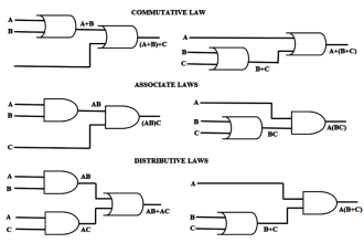
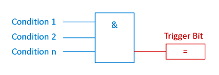
In most cases, alert-states are boolean (True, False) and triggered by certain conditions as displayed below.

For example, the trigger bit for the alert ‘overpressure’ becomes TRUE, if Condition 1 ‘pressure switch 1’, Condition 2 ‘pressure sensor value over critical threshold’, through n., are TRUE.

alert-states in PLC

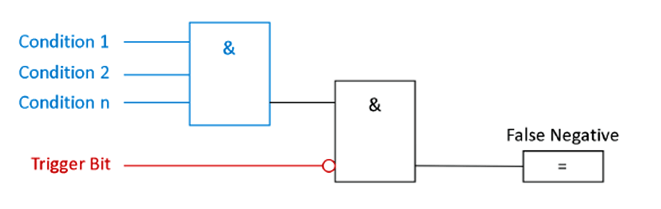
To masquerade an attack, an adversary could suppress the alert trigger bit and cause a false negative.

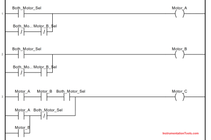
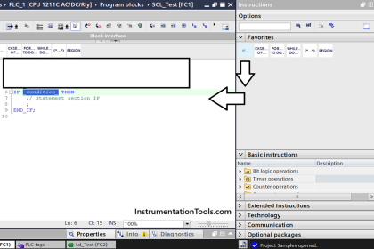
A trap for false negatives monitors the conditions for the trigger bit and the negated trigger bit itself. With this simple setup, a false negative is detected. See the following picture:

False Negative Logic in PLC

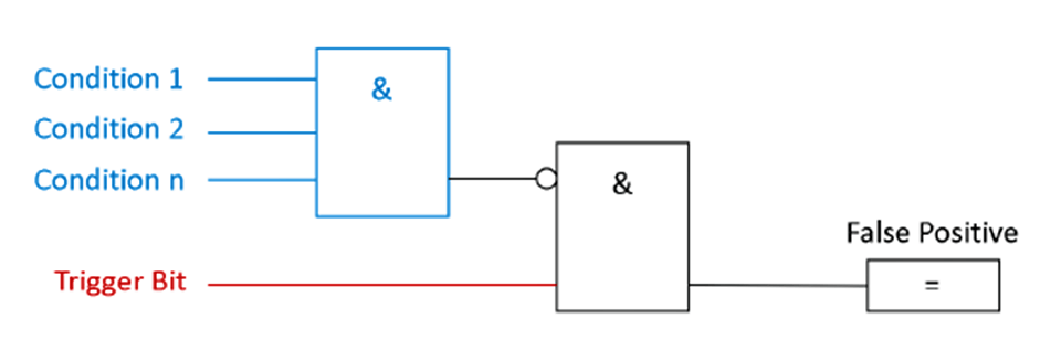
In other cases, an adversary could deliberately cause false positives, to wear down the process operator’s attention.

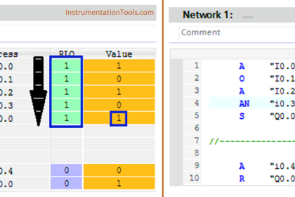
In the same manner of the false negative trap, false positives can also be detected by monitoring the alert trigger bit and if the trigger conditions are met. If the conditions are NOT met, but the trigger bit is active, a false positive is detected: See the following picture:

False Positive PLC Logic

Example 1

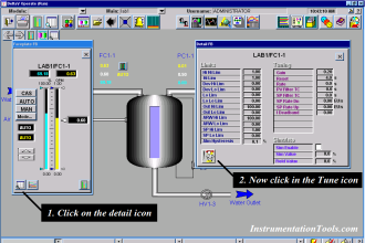
Siemens offers in their Siemens S7-1200/1500 Products a Webserver with a wide range of functions, for example, display of the PLC-State, cycle time, or scope records.

It also has the option to view and modify data tables and variables. The access rights to the Webserver can be modified in the PLC-Hardware Settings.

In case of mis-configured access rights, an adversary could gain access to the PLC Variables and Datablocks. To create a false positive, the adversary selects an alert trigger bit and alters the state.

Example 2

In the Triton/Trisys/HatMan attack, rogue code suppressed alert states.

Example 3

A bus-injection attack could send a false positive alert to a high-level SCADA client.

Why?

Beneficial for…?Why?
    SecurityMitigates false negative or false positives of critical alert messages caused by an adversary obfuscating their attack (i.e., rogue code, bus injection, tampering with accessible PLC state tables on unsecured web servers).
Reliability/
Maintenance/

References

Standard/frameworkMapping
MITRE ATT&CK ICSTactic : TA009 – Inhibit Response Function
Technique:  T0878 – Alarm Suppression
ISA 62443-3-3SR 3.5: Input Validation
ISA 62443-4-2CR 3.5: Input Validation
ISA 62443-4-1SI-1: Security implementation review
MITRE CWECWE-754: Improper Check for Unusual or Exceptional Conditions

Source: PLC Security

Don't Miss Our Updates
Be the first to get exclusive content straight to your email.
We promise not to spam you. You can unsubscribe at any time.
Invalid email address
You've successfully subscribed !
Sink or Source? Normally Open or Normally Closed?
Types of Script in Intouch Scada
Motor Feedback Fail Logic in PLC
FactoryTalk View Studio – Import and Export Tutorial
System Cabinet Health Checks – PLC and DCS Industrial Automation
Share This Article
Facebook Whatsapp Whatsapp LinkedIn Copy Link
Share
Leave a Comment

Leave a Reply Cancel reply

Your email address will not be published. Required fields are marked *

Stay Connected

128.3kFollowersLike
69.1kFollowersFollow
208kSubscribersSubscribe
38kFollowersFollow

Categories

Recent Comments

  • Guifty Shimica on Top Non-PLC Certification Courses for Automation Professionals
  • Guifty Shimica on Top Non-PLC Certification Courses for Automation Professionals
  • MIHARITSOA Aina Sitraka on Top Non-PLC Certification Courses for Automation Professionals
  • Vaishnavi on Free Instrumentation Course for Trainee Engineers

Related Articles

SCADA System

What is SCADA System?

Use Cryptographic checks for PLC

#5 PLC Best Practices – Cryptographic and Checksum Integrity Checks

Conveyor Control with Main Motor and Backup Motor

Conveyor Operation with a Backup Motor using PLC Ladder Diagram

Use PLC Flags as Integrity Checks

#4 PLC Best Practices – Use PLC Flags as Integrity Checks

FBD Logic

Why different PLC Programming Languages were Developed?

PLC Control for Baking Machines Logic

PLC Programming for Baking with Auto and Manual Modes

traffic light plc program

Traffic Light Control using PLC Ladder Logic

DDE Protocol

What is the DDE Protocol?

More Articles

Instrumentation Documents

Instrument Document Quiz

Error sources creating Uncertainty in calibration

Error sources creating uncertainty in Calibration

Impulse Line Pressure Testing Procedure

Impulse Line Pressure Testing Procedure

ON DELAY TIMER AS OFF DELAY TIMER

How to Interchange ON Delay Timer and OFF Delay Timer in a PLC

Shorted Parallel Circuit

Parallel Short Circuit Faults

Sorting Defective Parts PLC Logic

Advanced PLC Programming for Defective Parts Sorting

Voting System in PLC

Voting Concept in Package Safety System

capacitor-filter-ripples

Ripple Voltage in Rectifiers

Follow US
All rights reserved. Reproduction in whole or in part without written permission is prohibited.
Welcome Back!

Sign in to your account

Username or Email Address
Password

Lost your password?