In 1821, German scientist Thomas Seeback conducted several experiments on electricity. He discovered that electric current will flow through a circuit comprising two dissimilar conductors, provided the junctions where these conductors join are maintained at different temperatures. However, Seeback was unable to explain the actual scientific reason behind this phenomenon, and wrongly concluded that flowing heat produced the same effect as flowing electricity.
Later, in 1834, Jean Peltier, a French watchmaker and part-time physicist, while analyzing the Seeback effect, noted that, heat could be absorbed at one junction of dissimilar metals and discharged at the other junction in the same circuit. Twenty years after this, William Thomson (Lord Kelvin) was able to scientifically explain both, the Seeback and Peltier effects, and prove the relationship between them.
However, interesting as it may have been, at that time, this phenomenon was considered to be no more than a mere laboratory experiment. Then, in 1930, when Russian scientists began re-investigating the earlier works on the thermoelectric effect, world interest in this phenomenon was again piqued, which led to the development of practical thermoelectric devices.
The Peltier effect is said to be the inverse of the Seeback effect. Therefore, in order to be able to understand how the Peltier effect works, let’s first examine the Seeback effect.
Seeback Effect
The Seeback effect is a phenomenon wherein a temperature gradient occurring between the two junctions formed by two dissimilar electric conductors or semiconductors causes a potential difference to be developed between them. This potential difference allows electric current to flow through the circuit. Thus, the Seeback effect states that, a temperature gradient will cause electric current to flow through a circuit.
Mathematically, if (T1 – T2) is the temperature difference between the two junctions of dissimilar metals, then, according to the Seeback effect, it will produce an Electromotive Force (Voltage) given by the following:
E = α (T1 – T2)
Note: α is the differential Seebeck coefficient or (thermo electric power coefficient) between the two conductors/semiconductors. It is positive when the direction of electric current is the same as the direction of thermal current.
Peltier Effect
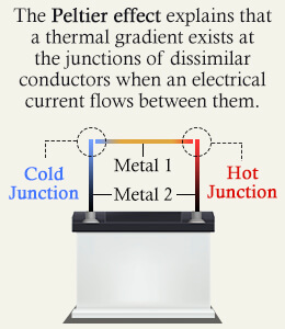
The Peltier effect states that, when an electric current flows through a circuit comprising dissimilar conductors, thermal energy is absorbed from one junction, and is discharged at the other, making the former cooler and the latter hotter. Thus, a thermal gradient develops from the flowing current, making the Peltier effect inverse of the Seeback effect.
If QC is the rate of cooling in watts, and QH is the rate of heating in watts, I is the current flowing through the closed circuit.
QC or QC = β x I
Note: β is the differential Peltier coefficient between the two materials A and B in volts.
The Peltier effect can be verified experimentally by using the following setup:
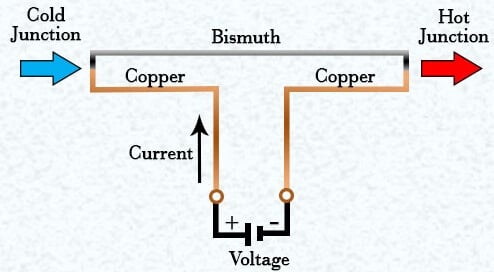
As shown, two pieces of copper wire are connected to the two terminals of a battery. These two pieces are then interconnected with the help of a bismuth wire, which completes the setup.
It is observed that when the circuit is closed, as described above, temperature gradient as predicted by the Peltier effect develops. At the junction where current passes from copper to bismuth, the temperature rises, while at the junction where current passes from bismuth to copper, the temperature drops.
How Does the Peltier Effect Work?
The Peltier effect occurs due to the fact that, the average energy of the electrons involved in the transfer of electric current is different for different conductors. It is dependent on several factors, including the energy spectrum of the electrons, their concentration in the conductor, and their scattering under the influence of applied voltage.
At the junction of two dissimilar conductors, the electrons pass from one conductor to another. Depending upon the direction of flow of electric charge, these electrons will either transfer their excess energy to the surrounding atoms, or absorb energy from them. As such, in the former, heat is dissipated, while in the latter, it is absorbed.
Advantages of Peltier Effect
1) The main advantage of the Peltier effect is that, it allows us to build cooling/heating devices that don’t have any moving parts, and therefore, are much less likely to fail as compared to conventional coolers and heaters. They also require almost no maintenance.
2) Peltier devices are silent in their operation, and can theoretically achieve temperatures as low as -80ºC (-176ºF).
3) The Peltier effect can be employed effectively at the microscopic level, where conventional cooling methods would not work.
Drawbacks of Peltier Effect
1) The major disadvantage of the Peltier effect is that, it is inefficient. The flowing current itself tends to generate a significant amount of heat, which gets added to the overall heat dissipation. In large applications, this results in an excessive amount of heat, which needs to be taken care of. Typically, additional fans have to employed to fix this problem.
2) This effect also uses a lot of electricity, which can make using it for large-scale applications very expensive.
3) If the components of Peltier devices are cooled too much, it can result in condensation, which may cause a short circuit.
Applications of the Peltier Effect
The Peltier effect is employed for building Peltier devices. These are solid-state devices that use this effect for cooling or heating. Commonly used devices include the Peltier heater, heat pump, cooler, and solid-state refrigerator.
When a direct current flows through a Peltier device, heat passes from one side of the device to another, allowing it to act as a heater or cooler. All Peltier devices function in this manner, by transferring heat from one side of the device to another against temperature gradient by using electric current.
The following are a few uses of Peltier devices:
1) Water Extraction: The Peltier effect is used in dehumidifiers for the process of extraction of water from the air.
2) DNA Synthesis: A thermal cycler make use of this effect for the process of DNA synthesis.
3) Spacecrafts: The Peltier effect is used in spacecrafts to balance the effects of sunlight on both sides of the craft. It helps in dissipating the heat due to direct sunlight on one side of the spacecraft to the other side which doesn’t receive sunlight, and so is much cooler.
Also Read: Introduction to RTD’s