Inst ToolsInst ToolsInst Tools
  • Courses
  • Automation
    • PLC
    • Control System
    • Safety System
    • Communication
    • Fire & Gas System
  • Instrumentation
    • Design
    • Pressure
    • Temperature
    • Flow
    • Level
    • Vibration
    • Analyzer
    • Control Valve
    • Switch
    • Calibration
    • Erection & Commissioning
  • Interview
    • Instrumentation
    • Electrical
    • Electronics
    • Practical
  • Q&A
    • Instrumentation
    • Control System
    • Electrical
    • Electronics
    • Analog Electronics
    • Digital Electronics
    • Power Electronics
    • Microprocessor
  • Request
Search
  • Books
  • Software
  • Projects
  • Process
  • Tools
  • Basics
  • Formula
  • Power Plant
  • Root Cause Analysis
  • Electrical Basics
  • Animation
  • Standards
  • 4-20 mA Course
  • Siemens PLC Course
Reading: Parking Garage Indicator: PLC Automation System
Share
Font ResizerAa
Inst ToolsInst Tools
Font ResizerAa
  • Courses
  • Design
  • PLC
  • Interview
  • Control System
Search
  • Courses
  • Automation
    • PLC
    • Control System
    • Safety System
    • Communication
    • Fire & Gas System
  • Instrumentation
    • Design
    • Pressure
    • Temperature
    • Flow
    • Level
    • Vibration
    • Analyzer
    • Control Valve
    • Switch
    • Calibration
    • Erection & Commissioning
  • Interview
    • Instrumentation
    • Electrical
    • Electronics
    • Practical
  • Q&A
    • Instrumentation
    • Control System
    • Electrical
    • Electronics
    • Analog Electronics
    • Digital Electronics
    • Power Electronics
    • Microprocessor
  • Request
Follow US
All rights reserved. Reproduction in whole or in part without written permission is prohibited.
Inst Tools > Blog > PLC Tutorials > Parking Garage Indicator: PLC Automation System

Parking Garage Indicator: PLC Automation System

In the parking garage indicator, when a spot is empty and a vehicle approaches the gate, the buzzer activates and the barrier lifts.

Last updated: April 30, 2024 2:58 pm
Editorial Staff
PLC Tutorials
No Comments
Share
5 Min Read
SHARE

In the parking garage indicator, when a parking spot is empty and a vehicle approaches the gate, the buzzer activates, and the barrier lifts.

Contents
Parking Garage IndicatorPLC Automation SystemInputs and OutputsProgrammingLogic ExplainedSimulation ResultsWhen all parking spots are occupiedWhen the parking spot is vacant and the sensor detects a vehicle

Note: This PLC exercise can be used to learn the ladder logic programming.

Parking Garage Indicator

Problem Statement

Design a PLC ladder logic for the following application.

We are using Five Sensors to control the Full Indicator, Buzzer, and Barrier.

When all parking spots are occupied, a full indicator should be turned ON and also barrier should not be lifted. If the parking spot is vacant and when the vehicle is at the gate, then the buzzer will turn ON and the barrier will be lifted, both for 5 seconds.

PLC Automation System

This PLC programming video explains the parking garage indicator logic.

PLC Sample Programs - Parking Garage Indicator

Inputs and Outputs

Digital Inputs:

Sensor 1: I0.0

Sensor 2: I0.1

Sensor 3: I0.2

Sensor 4: I0.3

Digital Outputs:

Full Indicator: Q0.0

Buzzer: Q0.1

Barrier: Q0.2

Programming

Parking Garage Indicator PLC Automation

Logic Explained

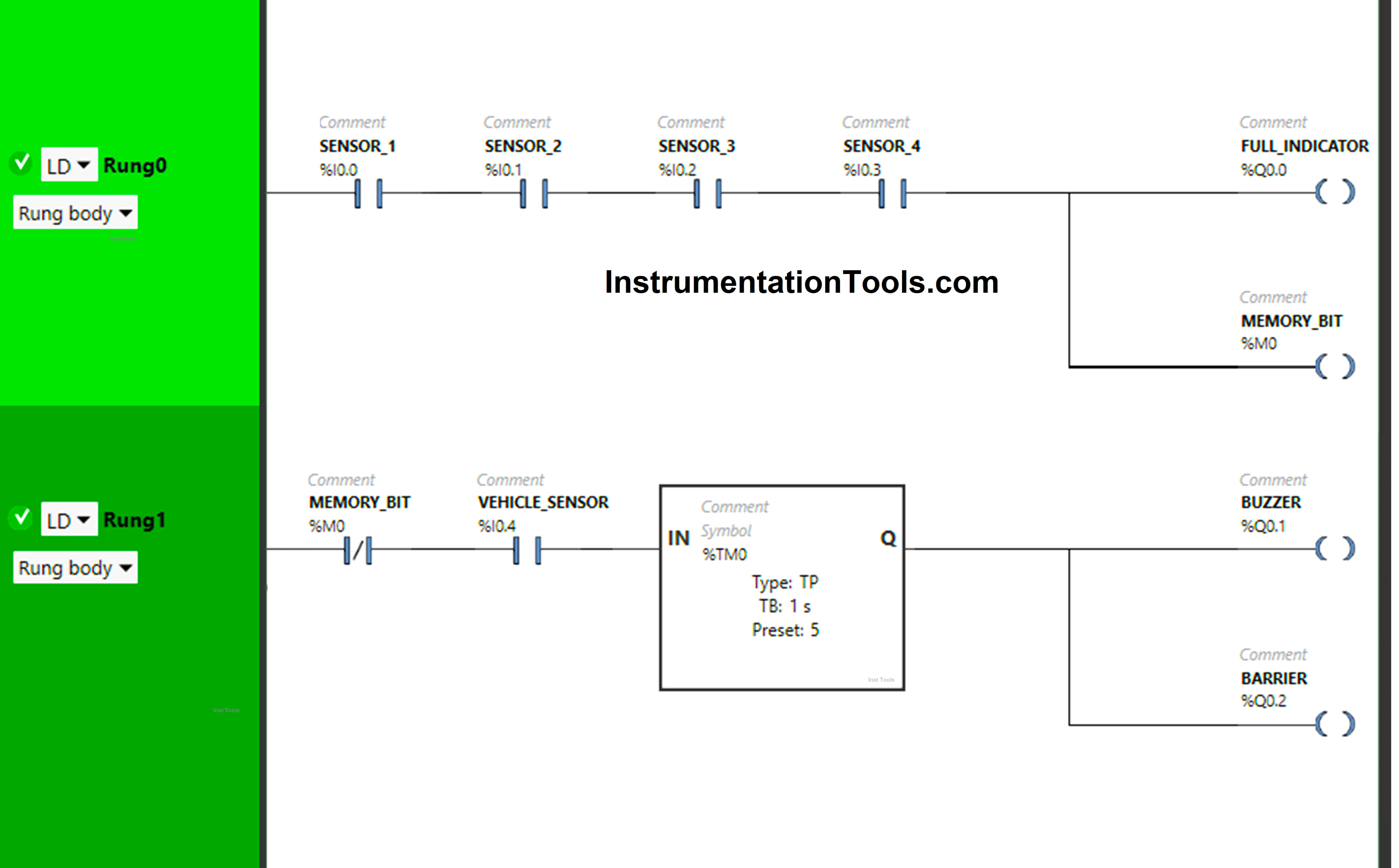
We have used Normally Open Contacts for Sensor 1 (I0.0), Sensor 2 (I0.1), Sensor 3 (I0.2), Sensor 4 (I0.3) and Vehicle Sensor (I0.4).

In Rung 0:

  1. Normally Open Contacts are used for Sensor 1 (I0.0), Sensor 2 (I0.1), Sensor 3 (I0.2), and Sensor 4 (I0.3) to Turn ON the output Full Indicator (Q0.0) and Memory Bit (M0).

In Rung 1:

  1. Normally Closed Contact is used for Memory Bit  (M0) to Turn ON the outputs Buzzer (Q0.1) and Barrier (Q0.2).
  2. Normally Open Contact is used for the Vehicle Sensor (I0.4) to Turn ON the output Buzzer (Q0.1) and Barrier (Q0.2).
  3. Timer TP is used to Turn ON the outputs Buzzer (Q0.1) and Barrier (Q0.2) for a limited time.

Simulation Results

Test our PLC program and analyze the simulation results.

When all parking spots are occupied

When Sensor 1 (I0.0), Sensor 2 (I0.1), Sensor 3 (I0.2), and Sensor 4 (I0.3) get activated in Rung0 (All parking spots occupied).

PLC Example on Parking Garage Indicator

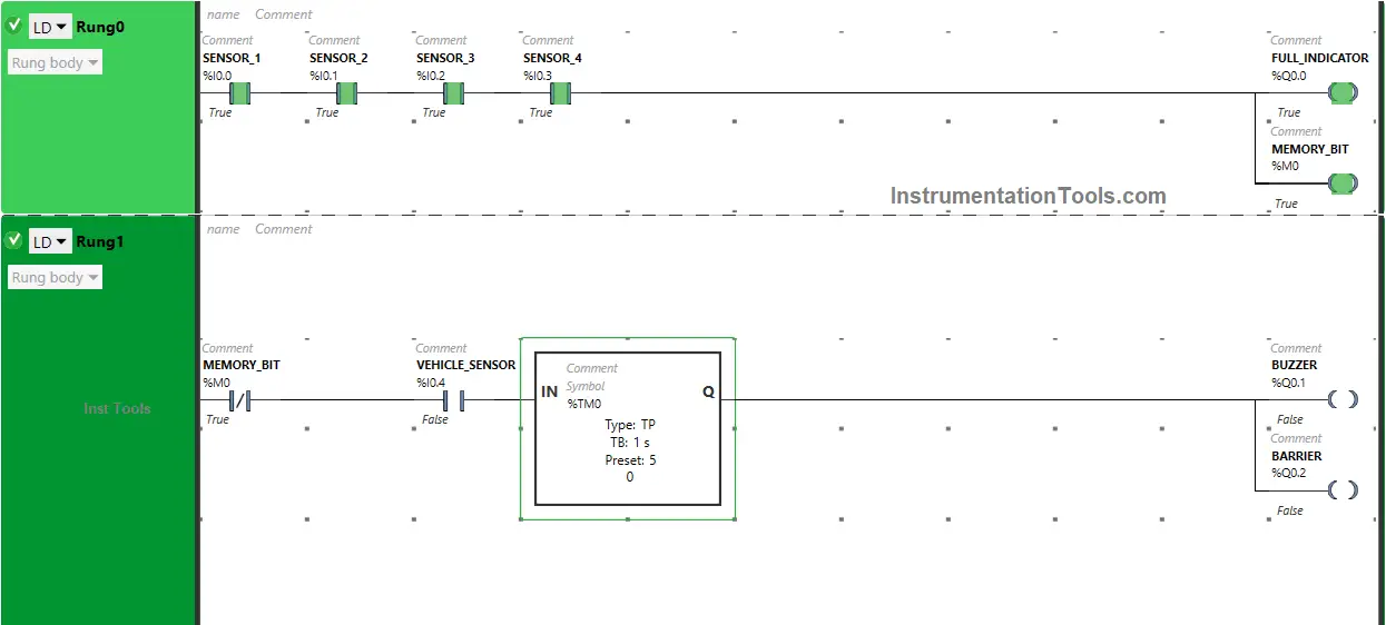
Then the output Full indicator (Q0.0) and Memory Bit (M0) turn ON as Normally Open Contacts used for Sensor 1 (I0.0), Sensor 2 (I0.1), Sensor 3 (I0.2), Sensor 4 (I0.3) will be in True state and allows the signal to pass through it and the output Full indicator (Q0.0) and Memory Bit (M0) will turn ON.

When the parking spot is vacant and the sensor detects a vehicle

When one or more than one sensor in Rung0 gets deactivated (one or more than one parking spot is vacant) (e.g Sensor 2 {I0.1} second spot), the output Full indicator (Q0.0) and Memory Bit (M0) turns OFF as Normally Open Contact used for Sensor 2 (I0.1) will be in False state and does not allow the signal to pass through it and the output Full indicator (Q0.0) and Memory Bit (M0) will turn OFF.

Parking Lot Control with PLC Simulator

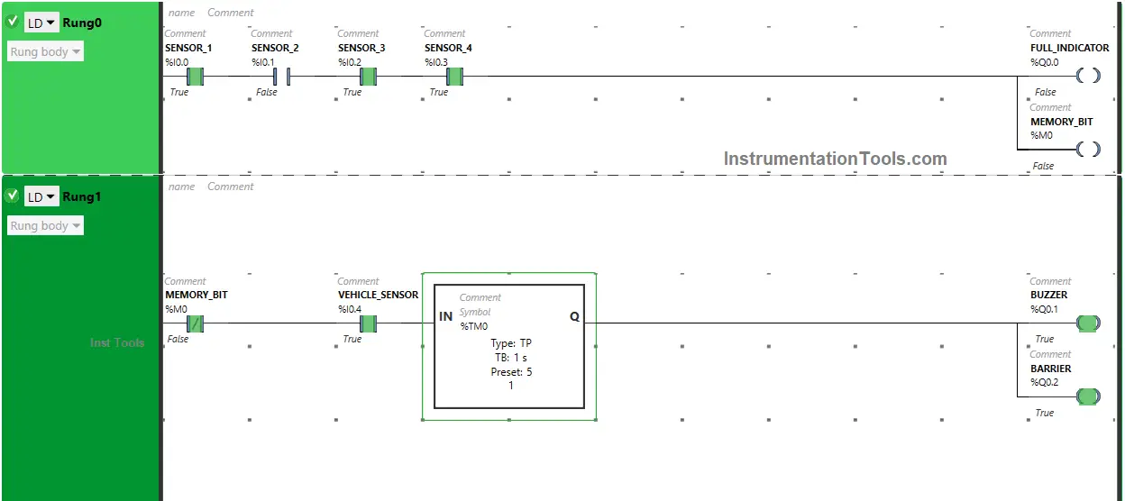
When Memory Bit (M0) turns OFF in Rung0, Normally Closed Contact used for Memory Bit (M0) in Rung1 will be in a False state and allow the signal to pass through it.

So, When Memory Bit (M0) in Rung1 is in False State and Vehicle Sensor (I0.1) gets activated (Sensor detects Vehicle ), the output Buzzer (Q0.1) will turn ON.

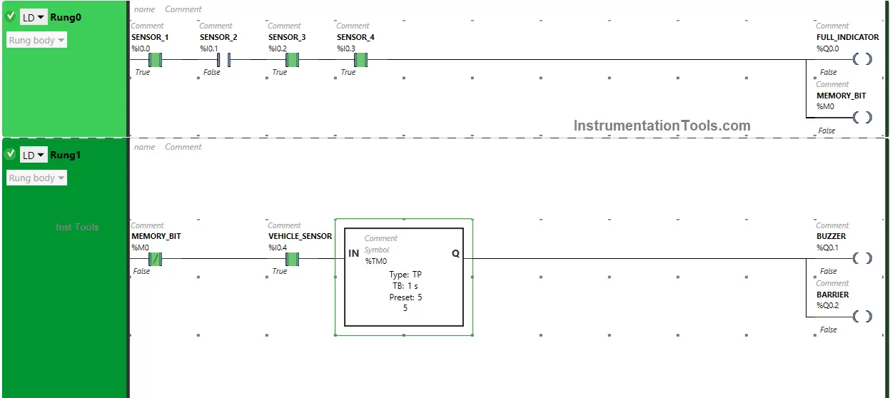
The output Barrier (Q0.2) will also turn ON (Barrier will be lifted) but only for 5 seconds as Timer Function Block type TP is used to turn ON the outputs Buzzer (Q0.1) and Barrier (Q0.2) for a limited time.

The time is set to 5 seconds. After 5 seconds, the outputs Buzzer (Q0.1) and Barrier (Q0.2) will turn OFF.

Automated Parking System using a PLC

If you liked this article, please subscribe to our YouTube Channel for PLC and SCADA video tutorials.

You can also follow us on Facebook and Twitter to receive daily updates.

Read Next:

  • Connecting Faceplate to PLC Project Tutorial
  • Automatic Car Washing using PLC Programming
  • PLC Program for Curtains and Stage Elevation
  • PLC Program Sorting Boxes by Height Ladder Logic
  • How to Use an SQL Server with Indusoft Web Studio?
Don't Miss Our Updates
Be the first to get exclusive content straight to your email.
We promise not to spam you. You can unsubscribe at any time.
Invalid email address
You've successfully subscribed !

Continue Reading

How to use PLC with SQL Database? – Basics & Tutorials
How to Configure PID Controller in Various Schneider PLCs?
PLC Program for Alarm Security System
Memory Structure of Siemens PLC
Test and Process Modes in Siemens PLC
#2 PLC Best Practices – Track Operating Modes
Share This Article
Facebook Whatsapp Whatsapp LinkedIn Copy Link
Share
Leave a Comment

Leave a Reply Cancel reply

Your email address will not be published. Required fields are marked *

Stay Connected

128.3kFollowersLike
69.1kFollowersFollow
210kSubscribersSubscribe
38kFollowersFollow

Categories

Explore More

Omron PLC for Product Painting with Integrated Weighing System
PLC Programming Example on Bottle Line Control
Main differences between Sinking and Sourcing Circuits
PLC Ladder Logic for Lube Oil Pump Motor
PLC Programming for Loss in Weight Liquid Systems
PLC FBD Program for Bottle’s Capping with Rotating Mechanism
CX Programmer Example: Perfume Mixing and Filling System
PLC Motor Logic with START, STOP, TEST Push buttons

Keep Learning

Principle of Operation of PLC

Principle of Operation of PLC

What is a GSD File and Why it is required?

What is a GSD File and Why it is required?

Structured Control Language (SCL) Elements

Value Assignments in SCL Language – Single, Multiple, Combined

Difference Between SCADA and HMI

Difference Between SCADA and HMI

How to Upload PLC Program in Siemens PLC if Upload Icon is Disabled

Upload Option Disabled in Siemens PLC

Field Instruments

#11 PLC Best Practices – Instrument for Plausibility Checks

Pneumatic valve operation in sequence mode

Sequential PLC Programming for the Pneumatic Valves

How to Get a PLC Programming Job With No Experience

How to Get a PLC Programming Job With NO Experience?

Learn More

Troubleshooting a Biased Transistor

Troubleshooting a Biased Transistor

Pressure and Temperature Gauges

Pressure and Temperature Gauges

water seal drum lever transmitter

Determine LRV and URV settings for the Level Transmitter

control of level in three cascaded Loops

Multiple Lags (orders)

Why Silicon is preferred over Germanium ?

Why Silicon is preferred over Germanium ?

Why Armature is placed on Stator for Synchronous machines

Water Treatment Control System

Waste Water Control System

Differential Pressure Transmitter Manifold

Field Instrument Calibration Errors

Menu

  • About
  • Privacy Policy
  • Copyright

Quick Links

  • Learn PLC
  • Helping Hand
  • Part Time Job

YouTube Subscribe

Follow US
All rights reserved. Reproduction in whole or in part without written permission is prohibited.
Welcome Back!

Sign in to your account

Username or Email Address
Password

Lost your password?