Inst ToolsInst ToolsInst Tools
  • Courses
  • Automation
    • PLC
    • Control System
    • Safety System
    • Communication
    • Fire & Gas System
  • Instrumentation
    • Design
    • Pressure
    • Temperature
    • Flow
    • Level
    • Vibration
    • Analyzer
    • Control Valve
    • Switch
    • Calibration
    • Erection & Commissioning
  • Interview
    • Instrumentation
    • Electrical
    • Electronics
    • Practical
  • Q&A
    • Instrumentation
    • Control System
    • Electrical
    • Electronics
    • Analog Electronics
    • Digital Electronics
    • Power Electronics
    • Microprocessor
  • Request
Search
  • Books
  • Software
  • Projects
  • Process
  • Tools
  • Basics
  • Formula
  • Power Plant
  • Root Cause Analysis
  • Electrical Basics
  • Animation
  • Standards
  • 4-20 mA Course
  • Siemens PLC Course
Reading: Parallel Circuit Current Calculations
Share
Font ResizerAa
Inst ToolsInst Tools
Font ResizerAa
  • Courses
  • Design
  • PLC
  • Interview
  • Control System
Search
  • Courses
  • Automation
    • PLC
    • Control System
    • Safety System
    • Communication
    • Fire & Gas System
  • Instrumentation
    • Design
    • Pressure
    • Temperature
    • Flow
    • Level
    • Vibration
    • Analyzer
    • Control Valve
    • Switch
    • Calibration
    • Erection & Commissioning
  • Interview
    • Instrumentation
    • Electrical
    • Electronics
    • Practical
  • Q&A
    • Instrumentation
    • Control System
    • Electrical
    • Electronics
    • Analog Electronics
    • Digital Electronics
    • Power Electronics
    • Microprocessor
  • Request
Follow US
All rights reserved. Reproduction in whole or in part without written permission is prohibited.
Inst Tools > Blog > Electrical Theory > Parallel Circuit Current Calculations

Parallel Circuit Current Calculations

Last updated: July 23, 2018 12:57 pm
Editorial Staff
Electrical Theory
No Comments
Share
2 Min Read
SHARE

The sum of the currents flowing through each branch of a parallel circuit is equal to the total current flow in the circuit.
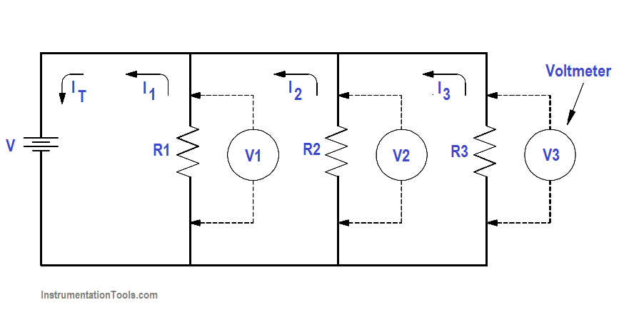
Parallel Circuit

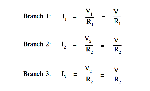
Using Ohm’s Law, the branch current for a three branch circuit equals the applied voltage divided by the resistance as shown in below equations.

Parallel Circuit Parallel Current Calculations

Example 1:

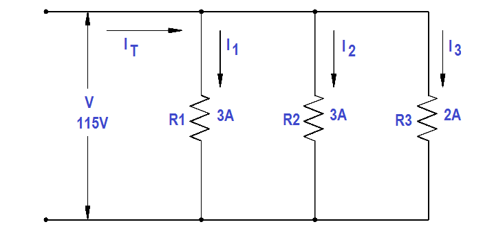
Two resistors, each drawing 3A, and a third resistor, drawing 2A, are connected in parallel across a 115 volt source (Figure 23). What is total current?

Parallel Resistance Circuit Current Calculations

Figure 23 Example 1 Parallel Circuit

IT = I1 + I2 + I3

IT = 3 + 3 + 2 = 8 A

Example 2:

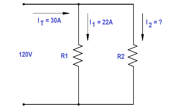
Two branches, R 1 and R2 , are across a 120 V power source. The total current flow is 30 A (Figure 24). Branch R1 takes 22 amps. What is the current flow in Branch R2 ?

Parallel Circuit Current Flow Calculations

Figure 24 Example 2 Parallel Circuit

Solution :

IT = I1 + I2

I2 = IT – I1

I2 = 30 -22 = 8A

Example 3:

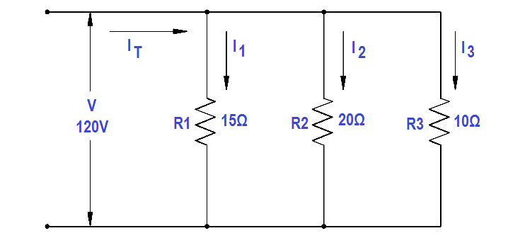
A parallel circuit consists of R1 =15Ω, R2 =20Ω and R3 =10Ω, with an applied voltage of 120 V (Figure 25). What current will flow through each branch?

Parallel Circuit Current Equation

Figure 25 Example 3 Parallel Circuit

Solution :

I1 = V/R1 = 120/15 = 8A

I2 = V/R2 = 120/20 = 6A

I3 = V/R3 = 120/10 = 12A

IT = I1 + I2 + I3 

IT = 8 + 6+ 12 = 26 A
Don't Miss Our Updates
Be the first to get exclusive content straight to your email.
We promise not to spam you. You can unsubscribe at any time.
Invalid email address
You've successfully subscribed !

Continue Reading

Ampere Hour Meter
Impedance in RL Circuits
Transformer Theory of Operation
Wattmeter
Inductive Time Constant
Single Line Diagram
Share This Article
Facebook Whatsapp Whatsapp LinkedIn Copy Link
Share
Leave a Comment

Leave a Reply Cancel reply

Your email address will not be published. Required fields are marked *

Stay Connected

128.3kFollowersLike
69.1kFollowersFollow
210kSubscribersSubscribe
38kFollowersFollow

Categories

Explore More

Transformer Voltage Ratio
Calculate Power in Parallel RL Circuit
AC Generation Analysis : Effective Values, Phase Angle and Frequency
How to Measure Specific Gravity of Battery
Motor Controllers
Electro-Dynamo Meter Movement
Rectifiers, Forward Bias and Reverse Bias
4-Wire, Three-Phase Wye Wiring System

Keep Learning

Split Phase Motor

Single Phase AC Induction Motors

Armature Current in a DC Motor

DC Motor Torque

Transformer Operation Under No-Load

Transformer Operation Under No-Load

Potential Difference Across a Conductor Causes a Current to Flow

Conductor, Insulator, Resistor and Current Flow

Capacitor and Symbols

Capacitance

Capacitive Time Constant for Charging Capacitor

Capacitive Time Constant

Electrical Component Symbols

Electrical Diagrams and Schematics

Electric Short Circuit

Series Short Circuit Faults

Learn More

Electrical Equipment Selection in Hazardous Area

Hazardous Areas in Industry – Electrical Equipment Selection

Interview Questions on Industrial Wireless

Interview Questions on Industrial Wireless

phototransistor-circuit

Phototransistor Circuit Example

Pump and Mixer Operations Example PLC Timer-Based Control

Pump and Mixer Operations Example: PLC Timer-Based Control

Contextual HMI

What is Contextual HMI? – HMI Screens on a Mobile or Tablet

Pressure Reducing and Desuperheating Station (PRDS)

Pressure Reducing and DeSuperheating Station (PRDS)

How to Convert Cable Size from AWG to Inches

How to Convert Cable Size from AWG to Inches

Control system architecture diagrams

Vendor Document for Project Systems Architecture

Menu

  • About
  • Privacy Policy
  • Copyright

Quick Links

  • Learn PLC
  • Helping Hand
  • Part Time Job

YouTube Subscribe

Follow US
All rights reserved. Reproduction in whole or in part without written permission is prohibited.
Welcome Back!

Sign in to your account

Username or Email Address
Password

Lost your password?