Here we shall see detailed specifications of the orifice type of flow meter.
Orifice metering is the standard measurement choice for flow except for the following conditions
- where required accuracy is not obtained
- where flow rate varies in a wide range
- where allowable pressure drop is limited
- for high-viscosity liquids and slurries
- where other types of flow meters are more advantageous, like batching applications
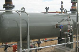
Orifice Specifications
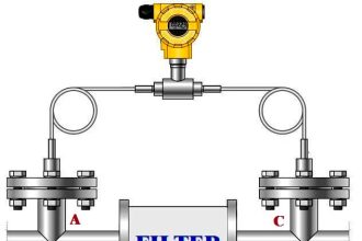
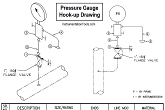
Generally, a square-edged concentric orifice plate mounted between a pair of weld neck flanges of minimum 300# ANSI rating for line size 2″ and above. Flange taps shall be used for line sizes up to 12″ while D-D/2 taps shall be used for line sizes 14″ and above.
The material of the orifice plates shall be normally SS 316, as a minimum. Orifice flange, gaskets, bolts & nuts material shall be as per the relevant Piping Material Specification.
Quadrant edge or quarter circle orifice plates shall be used for the following
- Highly viscous fluids
- Pipe Reynold’s no below 10000
- Beta Ratio<0.6
Conical entrance type of orifice plates shall preferably be used for the following
- Reynold’s No up to 250
- Beta Ratio < 0.3
Eccentric type of orifice should be generally used for multiphase flow and that too only in horizontal runs.
A vent and Drain hole are required is the bore diameter is > 25 mm.
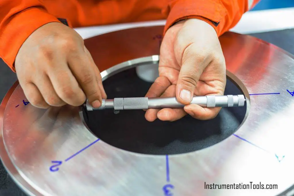
Orifice dimensions and machining tolerances should be according to BS 1042 Part 1 standard.
Sizing od orifice should be done in accordance with ISO 5167.
Integral orifice type transmitter shall be used in lines with 1½” (40 mm) nominal diameter or below. The integral flow assembly shall be supplied as an integral assembly consisting of upstream and downstream straight pipes, the integral orifice of 316 SS (as a minimum), and the transmitter installed along with the manifold.
End flanges shall be as per piping specifications. Upstream and downstream pipes shall be honed from the inside to achieve a smooth surface. Integral orifice meters, when used, shall be installed with block and bypass valves.
Upstream and Downstream straight run requirements are to be calculated considering the max beta ratio(0.75). Wherever this is not possible, you can calculate using the actual beta ratio given the codes allow it.
Orifice plates are mainly used for horizontal flow measurements however vertical flow measurement is allowed only in the downflow of vapors and liquids. Tapping of the orifice meter should be horizontal for liquids, condensable vapors, and steam.
The taps shall be on top for gas, non-condensable vapor, or liquids, which boil at or below the maximum design ambient temperature at operating pressure.
Each orifice plate shall be provided with a tab that is clearly visible in the final installed position and should clearly indicate the following details.
- Flow direction
- Flange size and rating
- Measured bore
- D. of the pipe
- Tag No
- Orifice plate material
Flanges should be according to ANSI B16.36 and generally, weld neck types are used.
Flanges above 3” should have a pair of jackscrews.
Orifice flanges used at pressure ratings up to 600 lb. shall be tapped ½” female NPT; for 900 lb. and above – ¾” female NPT. Orifice connections for Vena Contracta taps or pipe taps shall be ½” “Sockets” or equal. Material and schedule number of “Sockets” shall be in accordance with applicable piping specifications related to a specific service.
Max meter flow through orifice should be 1.5 times normal flow or 1.1 times maximum design flow.
Differential pressure ranges for orifice should not exceed 5000 mm of water. Where practical, the differential range will be 2500 mm (100 inches) water column. Other preferred ranges are 500, 625, 1250, 5000 mm of water.
The diameter ratio of orifice plates shall be as follows:
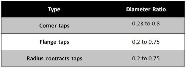
But generally, it is preferable that the Beta ratio should choose between 0.3 to 0.65.
Flow transmitter shall have 100:1 rangeability.
Interest to add any further points? Share with us through below comments section.
Author: Kalpit Patel
If you liked this article, then please subscribe to our YouTube Channel for Instrumentation, Electrical, PLC, and SCADA video tutorials.
You can also follow us on Facebook and Twitter to receive daily updates.
Read Next:
- Flowmeter Control Strategy
- What is Averaging Pitot Tube?
- Basics of Venturi Flow Meter
- Differential Pressure Flowmeter
- Flow Transmitter Square-Root