A relatively recent development in industrial flow measurement is Optical flow meter which uses light to measure the velocity of a fluid through a pipe.
One such technology referred to as Laser-Two-Focus (L2F) uses two laser beams to detect the passage of any light-scattering particles carried along by the moving fluid:
Optical Flow Meter

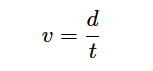
Where,
v = Velocity of particle
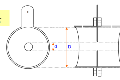
d = Distance separating laser beams
t = Time difference between sensor pulses
As a particle passes through each laser beam, it redirects the light away from its normal straight line path in such a way that an optical sensor (one per beam) detects up the scattered light and generates a pulse signal.
As that same particle passes through the second beam, the scattered light excites a second optical sensor to generate a corresponding pulse signal.
The time delay between two successive pulses is inversely proportional to the velocity of that particle.
This technique is analogous to the that used by law-enforcement officers to measure the speed of a vehicle on a highway when viewed from an aircraft: measure how much time elapses as the vehicle passes between two marks on the road spaced a known distance from each other.
L2F Flow Meter
L2F flow meters of course rely on the continual presence of light-scattering particles within the fluid.
These particles could be either liquid droplets or solids within a gas stream, or they could be solid particles or bubbles in a liquid stream.
An alternative to passing laser beams across the entire width of the pipe is to shrink the assembly down to the size of a probe which may be inserted into a pipe.
While minimizing installation and maintenance costs, this approach suffers the disadvantage of sensing velocity at only one point within the flow stream, much like a classic Pitot tube.
In order to obtain a measurement of bulk (average) fluid velocity, the raw velocity measurement provided by the sensor must be corrected based on the expected Reynolds number for the process fluid, which is why insertion L2F flowmeters are equipped with pressure and temperature transmitters in addition to the optical probe.
When the three measurements (pressure, temperature, and velocity at the probe) are combined, the Reynolds number may be calculated which then predicts how “flat” (consistent) the velocity profile is for the fluid stream:

For example, if the probe velocity, pressure, temperature, and dimensional parameters indicate a high Reynolds number, it means the velocity profile will be relatively flat, and thus the single-point velocity measurement at the probe will be a fair representation of velocity across the entire width of the pipe.
However, if the parameters indicate a low Reynolds number, it means the velocity profile will have a more pronounced “bullet” shape, and therefore the velocities near the pipe walls will be substantially less than the velocity at the center.
The flow computer uses this predicted velocity profile to interpret the probe’s single-point velocity measurement and calculate the average velocity of the entire flow stream.
Scintillation Flow Meter
A more sophisticated technique for optical flow measurement relies on the principle of scintillation, whereby the fluid itself warps the path of light passing through, rather than entrained particulate matter scattering the light.
Scintillation is the same phenomenon responsible for the “twinkling” of stars and city lights viewed from a long distance: as air passes between the light and the observer, pockets of air having different density (due to differences in temperature) and/or sufficient turbulence cause some of the light to be refracted away from an otherwise straight-line path, making it appear as though the light source is randomly vibrating or oscillating.
In fact, the phenomenon of scintillation has been used for the measurement of air velocity (anemometry) for many years before its application to industrial flow measurement.
Velocity measurements are inferred by a scintillation flowmeter much the same as they are by an L2F optical flowmeter: measuring the time difference between two sensors’ detection of the same scintillation pattern.
Therefore, the scintillation flowmeter applies the same basic formula v = d t to calculate fluid velocity.
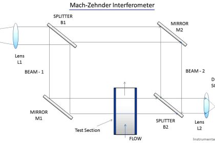
A simplified diagram of a scintillation flowmeter is shown here:

Scintillation-style optical flowmeters require a long optical path in order to maximize the angle at which light will be refracted.
Thus, they function best when used to measure across the full diameter of a pipe. An interesting feature of this flowmeter technology is that it functions best when the flow regime is highly turbulent, since increased fluid turbulence leads to greater scintillation.
Both L2F and scintillation flowmeters have phenomenal turndown ratios. At the low end of the velocity measurement range, an L2F meter is limited by the number of particles entrained in the flow stream and also by the random motions of particles which might be misinterpreted by the flowmeter as bulk motion of the fluid.
Scintillation flowmeters are limited at the low end of their measurement range by loss of turbulence, which of course is one of the driving mechanisms of the scintillation effect.
However, it should be noted that in both cases the low-velocity measuring limit is quite low in comparison to other types of flow meters.
With no moving parts and using light as the sensing medium, the upper limit for an optical flow meter can extend into supersonic velocities. This combination of excellent low-velocity and high-velocity sensing yields practical turndown ratios of 1000:1 or more.
Optical flow meters have been successfully used in one of the more challenging industrial flow measurement applications in existence: flare gas flow metering.
A “flare” is a continually-ignited burner used as a safety relief point for flammable gases in industries such as petroleum production and refining where a need exists to occasionally vent these gases to the atmosphere:

Ideally, flares operate with no flow of gas to them except during emergency conditions, and then when there is an emergency the flow rate can be very high.
In order to accurately measure the low “quiescent” flow of gas to a flare during non-emergency operation (due to pressure relief valve leakage and other inefficiencies) while still being able to register full flow rates during emergencies, the flowmeter must have an extremely large turndown ratio (rangeability).
Gas sent to a flare typically varies widely in composition, temperature, and pressure, especially when multiple processing units share a common flare.The random variability of the gas eliminates many types of flowmeters from consideration.
Pressure-based flowmeters such as orifice plates suffer from calibration errors due to density changes, as well as poor turndown ratio.
Thermal mass flow meters suffer from calibration errors due to changes in the specific heat value of the flare gas.
Velocity-based gas flow meters (e.g. turbine, vortex, ultrasonic) are not affected by compositional changes to the extent that pressure-based and thermal flow meters are, but few exhibit the degree of turndown necessary to accurately measure the full range of flare gas flow.
Multi-path transit-time ultrasonic flow meters show promise in this challenging application, but their relatively high cost (especially at the large pipe diameters typical of flare headers) is a limiting factor.
If you liked this article, then please subscribe to our YouTube Channel for Instrumentation, Electrical, PLC, and SCADA video tutorials.
You can also follow us on Facebook and Twitter to receive daily updates.
Read Next:
- Velocity Flow Meter Principle
- Laminar Flow Meter Principle
- Important Factors in Flow
- Doppler Flow Meter Disadvantages
- Basics of Vortex flow meters