A rectifier with an appropriate filter serves as a good source of d.c. output. However, the major disadvantage of such a power supply is that the output voltage changes with the variations in the input voltage or load. Thus, if the input voltage increases, the d.c. output voltage of the rectifier also increases. Similarly, if the load current increases, the output voltage falls due to the voltage drop in the rectifying element, filter chokes, transformer winding etc. In many electronic applications, it is desired that the output voltage should remain constant regardless of the variations in the input voltage or load. In order to ensure this, a voltage stabilising device, called voltage stabiliser is used. Several stabilising circuits have been designed but only zener diode as a voltage stabiliser.
A zener diode can be used as a voltage regulator to provide a constant voltage from a source whose voltage may vary over sufficient range. The circuit arrangement is shown in Fig (i). The zener diode of zener voltage Vz is reverse connected across the load RL across which constant output is desired. The series resistance R absorbs the output voltage fluctuations so as to maintain constant voltage across the load. It may be noted that the zener will maintain a constant voltage Vz (= E0) across the load so long as the input voltage does not fall below Vz
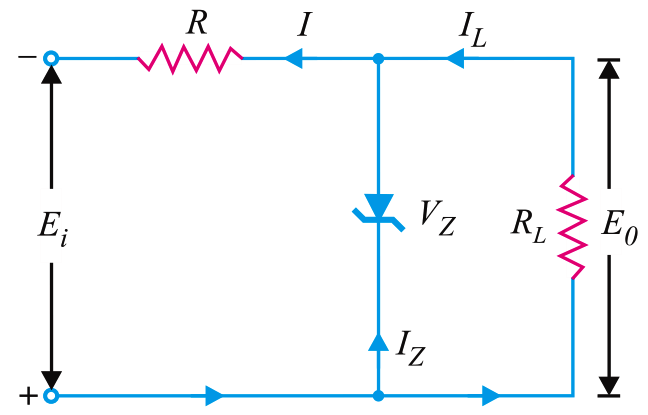
Fig (i)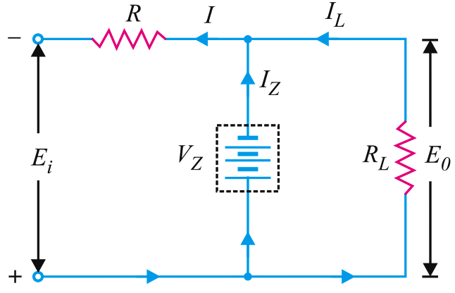
fig (ii)
When the circuit is properly designed, the load voltage E0 remains essentially constant (equal to Vz) even though the input voltage Ei and load resistance RL may vary over a wide range.
(i) Suppose the input voltage increases. Since the zener is in the breakdown region, the zener diode is equivalent to a battery VZ as shown in Fig (ii). It is clear that output voltage remains constant at VZ (= E0). The excess voltage is dropped across the series resistance R. This will cause an increase in the value of total current I. The zener will conduct the increase of current in I while the load current remains constant. Hence, output voltage E0 remains constant irrespective of the changes in the input voltage Ei.
(ii) Now suppose that input voltage is constant but the load resistance RL decreases. This will cause an increase in load current. The extra current cannot come from the source because drop in R (and hence source current I) will not change as the zener is within its regulating range. The additional load current will come from a decrease in zener current IZ. Consequently, the output voltage stays at constant value.
Voltage drop across R = Ei − E0
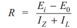
Current through R, I = IZ + IL
Applying Ohm’s law, we have