This article will discuss the use of various types of timer instructions in the Omron PLC. A timer is an instruction used to delay or control the execution time of an operation in a program. The timer operates based on a predefined duration (preset time). The CX-Programmer software includes four commonly used timer instructions: TIM, TIMX, TTIM, and TTIMX. To test their use, in this program, each timer instruction will be applied to turn ON a lamp with a specific preset time.
Program Objective
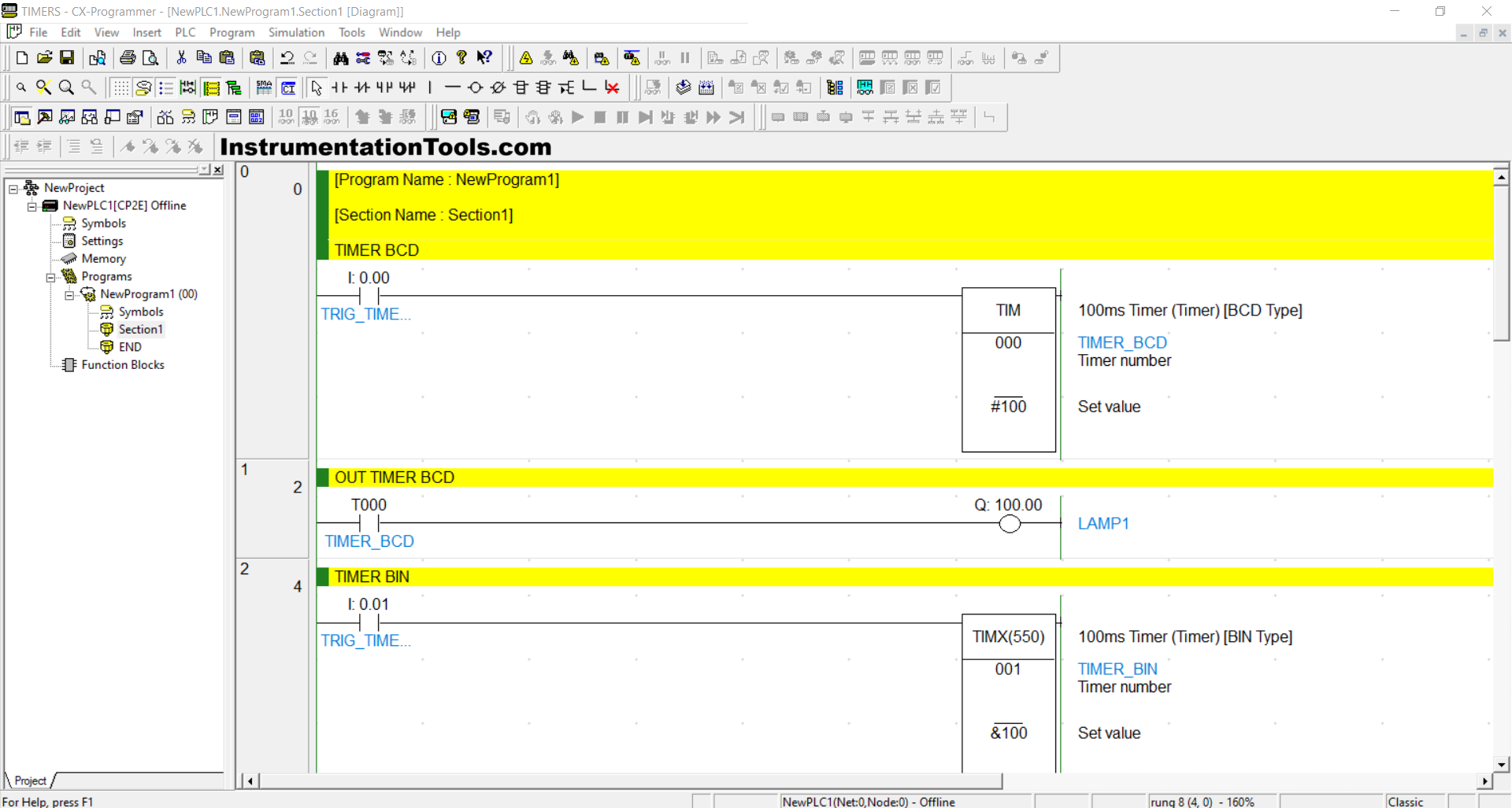
1. TIM Instruction
The TIM instruction is a countdown-type timer with a maximum preset time range of 0–9999.
- This instruction counts time in BCD (Binary Coded Decimal) format, so the preset time parameter must be written with the “#” prefix.
- The TIM instruction has only one input parameter to activate the instruction and will turn Off if it does not receive a trigger signal.
- TIM operates with a time interval of 0.1 seconds (100 ms) and does not retain historical time data.
- In this program, the timer’s preset time is set to 10 seconds by writing #100, and it will turn On Lamp 1.
2. TIMX(550) Instruction
The TIMX(550) instruction is a countdown-type timer with a maximum preset time of 0–65535 in decimal format or #0000–#FFFF in hexadecimal format.
- The preset time must begin with an “&” if written in decimal format or with a “#” if written in hexadecimal.
- The TIMX instruction has only one input parameter to activate the instruction and will turn Off without a trigger signal.
- TIMX has a time interval of 0.1 seconds (100 ms) and cannot store time history.
- In this program, the timer is set to 10 seconds using the value &100, and it will turn on Lamp 2.
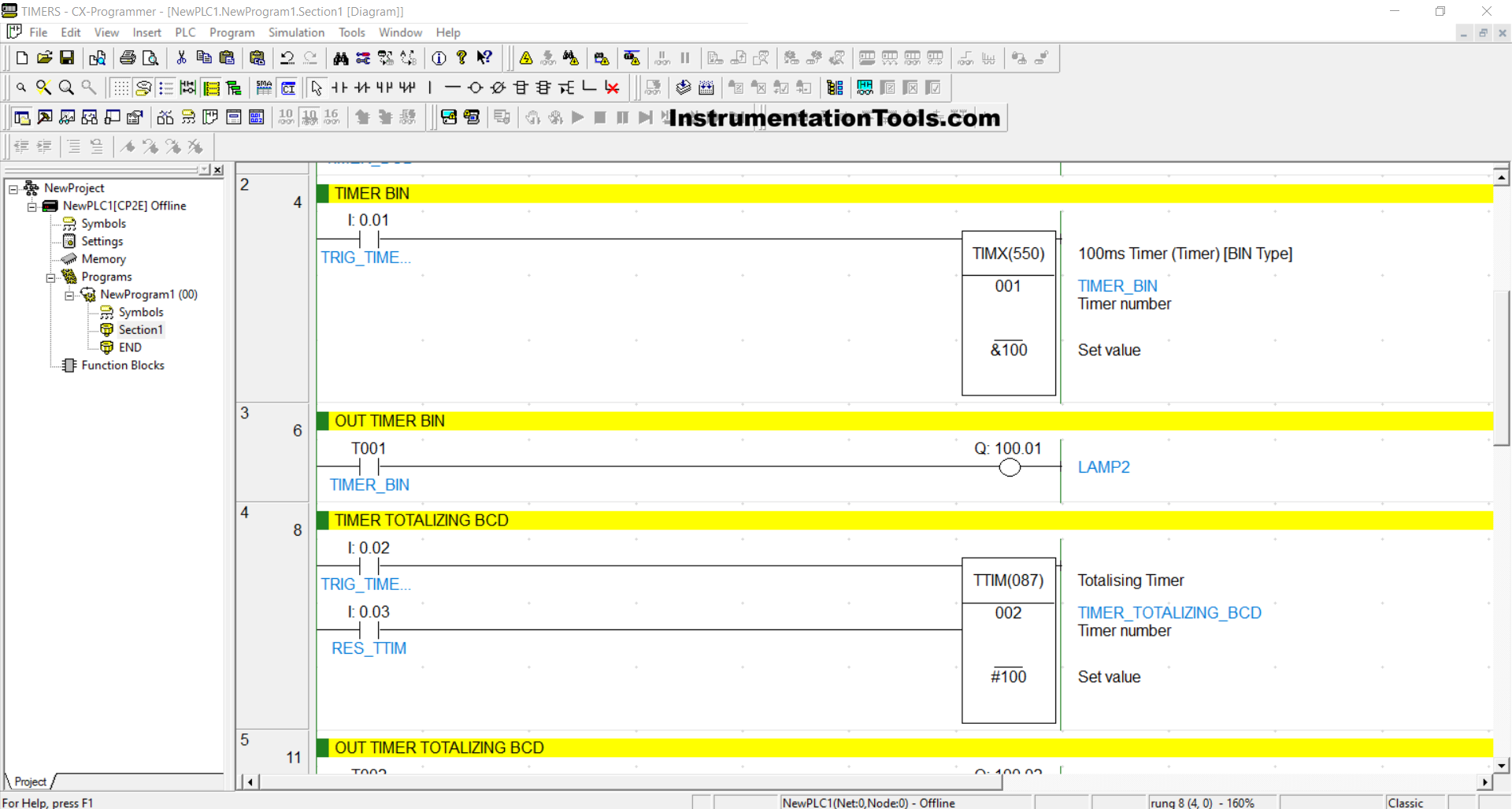
3. TTIM(087) Instruction
The TTIM(087) instruction is a count-up timer, also known as a Totalizing Timer, with a maximum preset time of 0–9999.
- This instruction also uses BCD (Binary Coded Decimal) format, requiring the preset time to be written with the “#” prefix.
- TTIM(087) has two input parameters: one to activate the instruction and one to reset the stored timer history.
- TTIM(087) operates with a 0.1 second (100 ms) interval and can save time history.
- In this program, the preset time is set to 10 seconds using #100, and it will turn On Lamp 3.
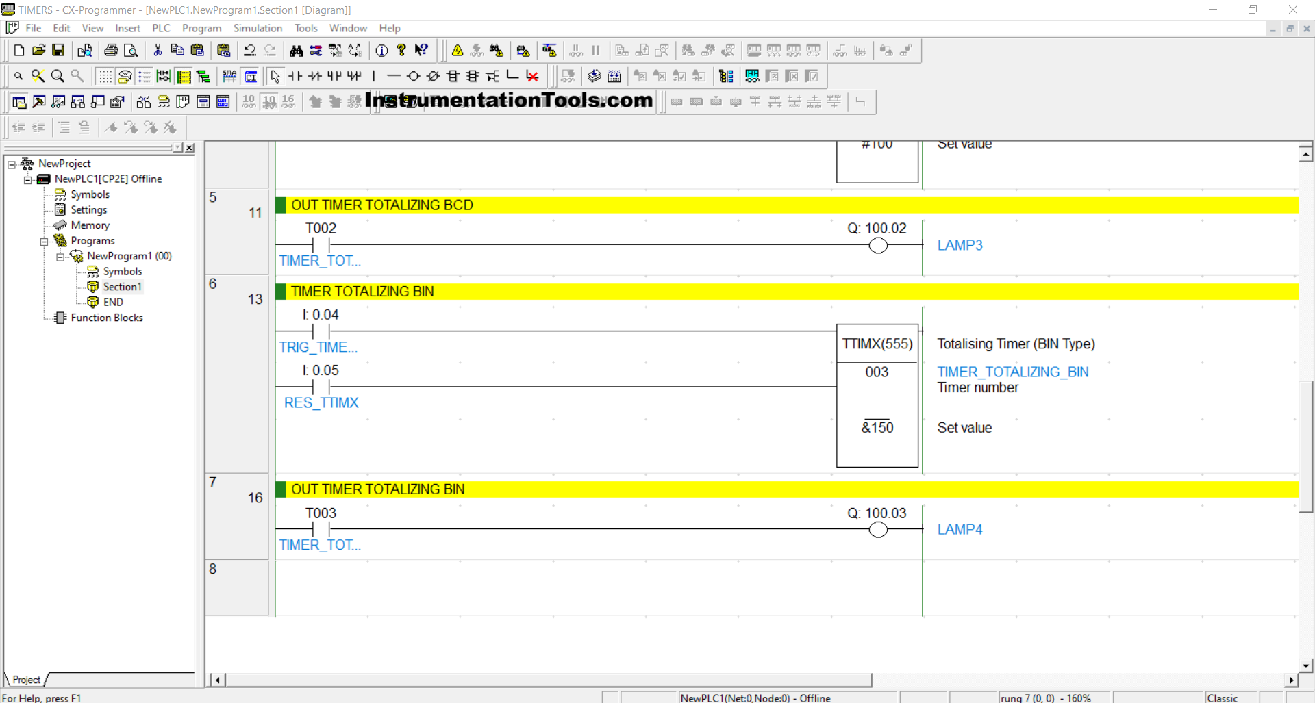
4. TTIMX(555) Instruction
The TTIMX(555) instruction is a count-up timer, also known as a Totalizing Timer, with a maximum preset time of 0–65535 in decimal or #0000–#FFFF in hexadecimal.
- The preset value must be prefixed with “&” for decimal or “#” for hexadecimal format.
- TTIMX(555) includes two input parameters: one to activate the instruction and one to reset the timer’s stored history.
- This timer operates at 0.1 second (100 ms) intervals and can save time history.
- In this program, the timer is set to 15 seconds using &150, and it will turn On Lamp 4.
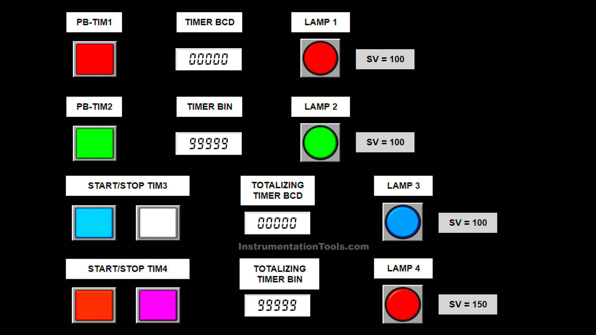
Omron PLC Timers
Simulation
In the video below, we simulated this PLC program of various timers and results displayed.
Mapping Details
| S.No. | Comment | Input (I) | Output(Q) | Timer |
|---|---|---|---|---|
| 1 | TRIG_TIMER1 | 0.00 | ||
| 2 | TRIG_TIMER2 | 0.01 | ||
| 3 | TRIG_TIMER3 | 0.02 | ||
| 4 | RES_TTIM | 0.03 | ||
| 5 | TRIG_TIMER4 | 0.04 | ||
| 6 | RES_TTIMX | 0.05 | ||
| 7 | LAMP1 | 100.00 | ||
| 8 | LAMP2 | 100.01 | ||
| 9 | LAMP3 | 100.02 | ||
| 10 | LAMP4 | 100.03 | ||
| 11 | TIMER_BCD | T000 | ||
| 12 | TIMER_BIN | T001 | ||
| 13 | TIMER_TOTALIZING_BCD | T002 | ||
| 14 | TIMER_TOTALIZING_BIN | T003 |
Omron PLC Timer Example
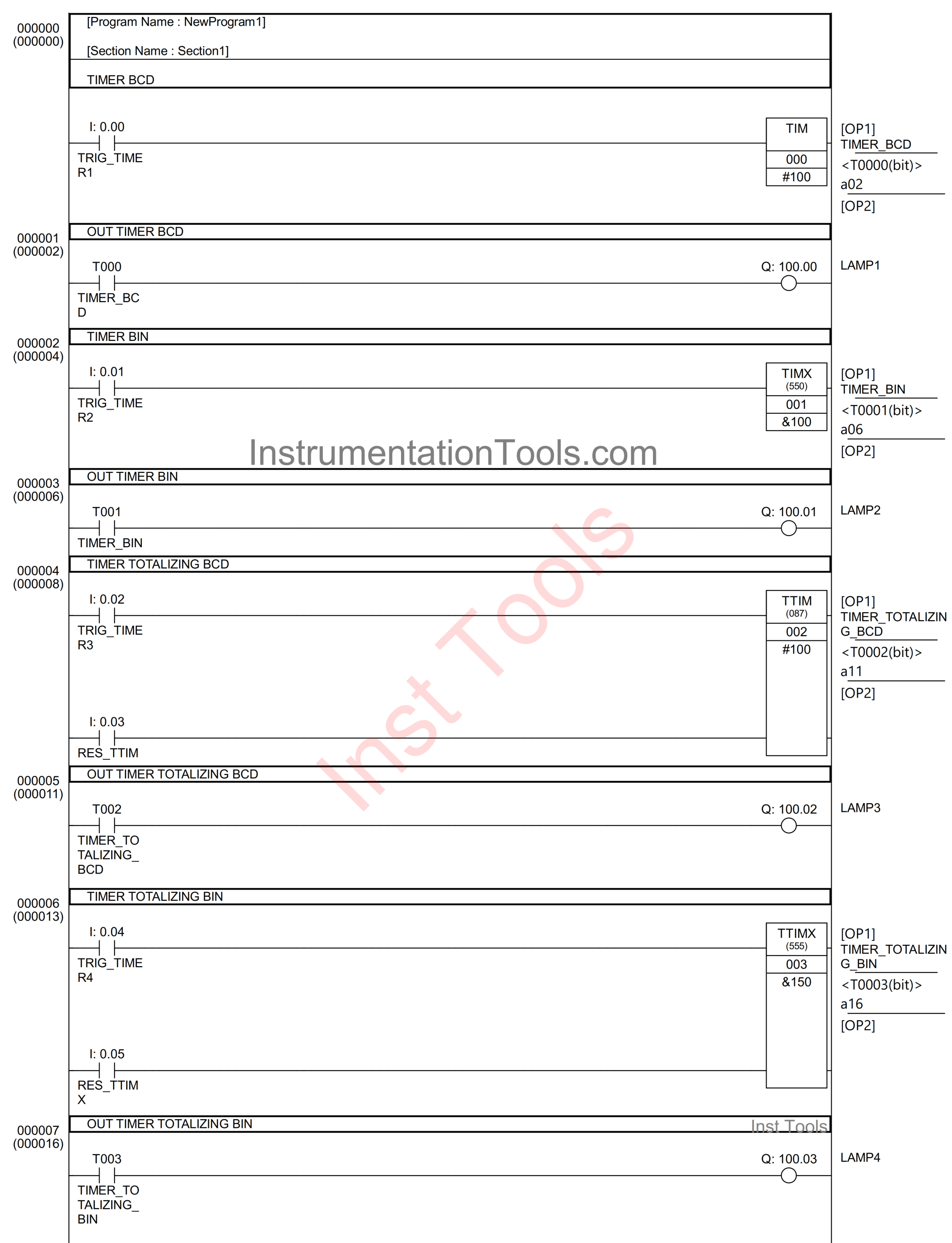
RUNG 0 (TIMER BCD)
In this Rung, if the TRIG_TIMER1 (0.00) button is pressed, then the TIMER_BCD (T000) timer instruction will start counting down for “10” seconds, and when it has finished counting, the TIMER_BCD (T000) timer instruction will be ON.
The TIMER_BCD (T000) timer instruction will be OFF if the TRIG_TIMER1 (0.00) button has been released.
RUNG 1 (OUT TIMER BCD)
In this Rung, the LAMP1 (100.00) output will be ON if the NO contact of TIMER_BCD (T000) is in the HIGH state.
RUNG 2 (TIMER BIN)
In this Rung, if the TRIG_TIMER2 (0.01) button is pressed, then the TIMER_BIN (T001) timer instruction will start counting down for “10” seconds, and when it has finished counting, the TIMER_BIN (T001) timer instruction will be ON.
The TIMER_BIN (T001) timer instruction will be OFF if the TRIG_TIMER2 (0.01) button has been released.
RUNG 3 (OUT TIMER BIN)
In this Rung, the LAMP2 (100.01) output will be ON if the NO contact of TIMER_BIN (T001) is in the HIGH state.
RUNG 4 (TIMER TOTALIZING BCD)
In this Rung, if the TRIG_TIMER3 (0.02) button is pressed, then the TIMER_TOTALIZING_BCD (T002) timer instruction will start counting up to “10” seconds, and when it has finished counting, the TIMER_TOTALIZING_BCD (T002) timer instruction will turn ON.
The TIMER_TOTALIZING_BCD (T002) timer instruction will only turn OFF if the RST_TTIM (0.03) button has been pressed.
RUNG 5 (OUT TIMER TOTALIZING BCD)
In this Rung, the output LAMP3 (100.02) will be ON if the NO contact of TIMER_BCD (T002) is in the HIGH state.
RUNG 6 (TIMER TOTALIZING BIN)
In this Rung, if the TRIG_TIMER4 (0.04) button is pressed, then the TIMER_TOTALIZING_BIN (T003) timer instruction will start counting up to “15” seconds, and when it has finished counting, the TIMER_TOTALIZING_BIN (T003) timer instruction will be ON.
The TIMER_TOTALIZING_BIN (T003) timer instruction will only be OFF if the RST_TTIMX (0.05) button has been pressed.
RUNG 7 (OUT TIMER TOTALIZING BCD)
In this Rung, the LAMP4 (100.03) output will be ON if the NO contact of TIMER_BIN (T003) is in the HIGH state.
Read Next:
- Introduction to Functional Block Diagrams
- How to Insert Block Calls in SCL Language?
- PLC FOR DO Statement in SCL Language
- Automation System for Hazardous Environments
- Mitsubishi FX3U PLC with Weinview MT6071iE HMI