In this article, you will learn the Omron PLC programming for product painting with integrated weighing system.
Product Painting with Integrated Weighing System
This program has 3 buttons, the START_SYSTEM (0.00) button is used to turn ON the system, the STOP_SYSTEM (0.01) button is used to turn OFF the system, the RESET _COUNTER (0.03) button is used to reset data in memory word RED_COUNTER (D5), GREEN_COUNTER (D6), and BLUE_COUNTER (D7).
Products carried by the conveyor will be painted in different colors, Red, Green, and Blue. The Color Sprayer will be Activate based on the weight of the product, when the product weight is “15kg” then the Red Sprayer will be ON, if the product weight is “20kg” then the Green Sprayer will be ON, and if the product weight is “25kg” then Blue Sprayer will be ON.
In this PLC program, when the START_SYSTEM (0.00) button is pressed, the system will Run and the CONVEYOR (100.00) output will be ON.
When the product carried by the Conveyor weighs “15kg”, the CONVEYOR (100.00) output will be OFF for 4 seconds and RED_SPRAYER (100.01) output will be ON for 4 seconds. Products that have been colored will be recorded in the memory word RED_COUNTER (D5).
When the product carried by the Conveyor weighs “20kg”, the CONVEYOR (100.00) output will be OFF for 4 seconds and the GREEN_SPRAYER (100.02) output will be ON for 4 seconds. Products that have been colored will be recorded in the memory word GREEN_COUNTER (D6).
When the product carried by the Conveyor weighs “25kg”, the CONVEYOR (100.00) output will be OFF for 4 seconds and the BLUE_SPRAYER (100.03) output will be ON for 4 seconds. Products that have been colored will be recorded in the memory word BLUE_COUNTER (D7).
The data in memory words RED_COUNTER(D5), GREEN_COUNTER (D6), and BLUE_COUNTER (D7) will be Reset if the RESET _COUNTER (0.03) button is Pressed.
Inputs and Outputs
| Comment | Input (I) | Output(Q) | Memory Bits | Memory Words | Timers |
| START_SYSTEM | 0.00 | ||||
| STOP_SYSTEM | 0.01 | ||||
| RESET_COUNTER | 0.03 | ||||
| CONVEYOR | 100.00 | ||||
| RED_SPRAYER | 100.01 | ||||
| GREEN_SPRAYER | 100.02 | ||||
| BLUE_SPRAYER | 100.03 | ||||
| TIMER_RED | T0000 | ||||
| TIMER_GREEN | T0001 | ||||
| TIMER_BLUE | T0002 | ||||
| SYSTEM_ON | W0.00 | ||||
| WEIGHING_INDICATOR | D0 | ||||
| RED_COUNTER | D5 | ||||
| GREEN_COUNTER | D6 | ||||
| BLUE_COUNTER | D7 |
Omron PLC System
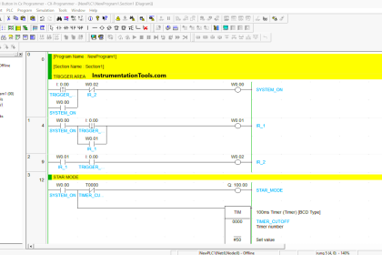
RUNG 0 (SYSTEM_ON)
In this Rung, when the START_SYSTEM (0.00) button is Pressed, the memory bit SYSTEM_ON (W0.00) will become a HIGH state. Because it uses the KEEP (011) instruction, the memory bit SYSTEM_ON (W0.00) remains in the HIGH state even though the START_SYSTEM (0.00) button has been Released.
The memory bit SYSTEM_ON (W0.00) will change to a LOW state if the STOP_SYSTEM (0.01) button is Pressed.
RUNG 1 (CONVEYOR ON)
When the NO contact of memory bit SYSTEM_ON (W0.00) is in the HIGH state, then the CONVEYOR (100.00) Output becomes ON. The CONVEYOR (100.00) output will be OFF if the NC contact of RED_SPRAYER (100.01) or GREEN_SPRAYER (100.02) or BLUE_SPRAYER (100.03) output is ON.
RUNG 2 (RED SPRAY)
In this Rung, when the NO contact of memory bit SYSTEM_ON (W0.00) in HIGH state and memory word WEIGHING_INDICATOR (D0) is equal to “15”, then the RED_SPRAYER (100.01) output will be ON and timer TIMER_RED (T0000) will Start counting up to 4 seconds.
The RED_SPRAYER (100.01) output will be OFF when the timer TIMER_RED (T0000) has finished counting. When the memory word WEIGHING_INDICATOR (D0) is not equal to “15”, then the timer TIMER_RED (T0000) will be Reset.
RUNG 3 (GREEN SPRAY)
In this Rung, when the NO contact of memory bit SYSTEM_ON (W0.00) in HIGH state and memory word WEIGHING_INDICATOR (D0) is equal to “20”, then the GREEN_SPRAYER (100.02) output will be ON and the timer TIMER_GREEN (T0001) will Start counting up to 4 seconds.
The GREEN_SPRAYER (100.02) output will be OFF when the timer TIMER_GREEN(T0001) has finished counting. When the memory word WEIGHING_INDICATOR (D0) has a value not equal to “20”, then the timer TIMER_GREEN (T0001) will be Reset.
RUNG 4 (BLUE SPRAY)
In this Rung, when the NO contact of memory bit SYSTEM_ON (W0.00) in HIGH state and memory word WEIGHING_INDICATOR (D0) is equal to “25”, then the BLUE_SPRAYER (100.03) output will be ON and the timer TIMER_BLUE (T0002) will Start counting up to 4 seconds.
The BLUE_SPRAYER (100.03) Output will be OFF when the TIMER_BLUE (T0002) timer has finished counting. When the memory word WEIGHING_INDICATOR (D0) has a value not equal to “25”, then the timer TIMER_BLUE (T0002) will be Reset.
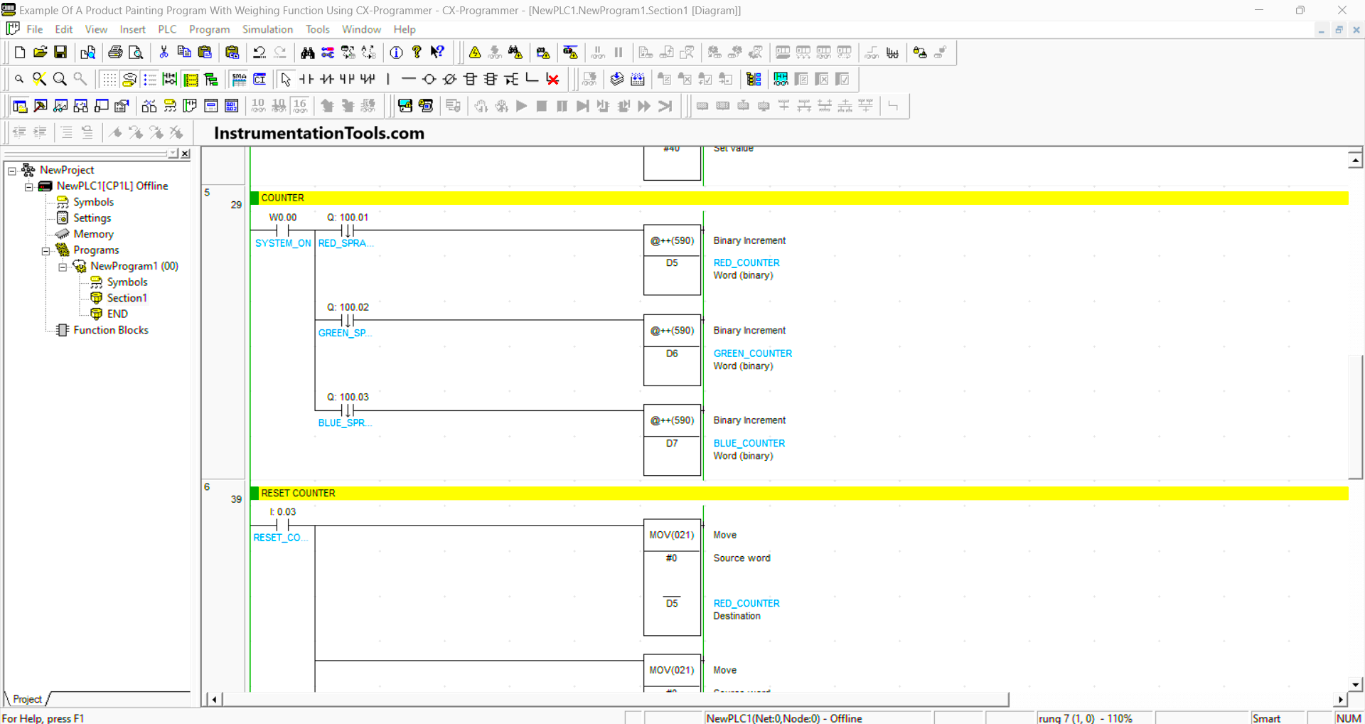
RUNG 5 (COUNTER)
When the NO contact of memory bit SYSTEM_ON (W0.00) is in a HIGH state and the NO contact of RED_SPRAYER (100.01) output is ON, then the value in memory word RED_COUNTER (D5) will increase (+1).
Or if the NO contact of GREEN_SPRAYER(100.02) output is ON, then the value in memory word GREEN_COUNTER (D6) will increase (+1).
Or if the NO contact of BLUE_SPRAYER (100.03) output is ON, then the value in memory word BLUE_COUNTER (D7) will increase (+1).
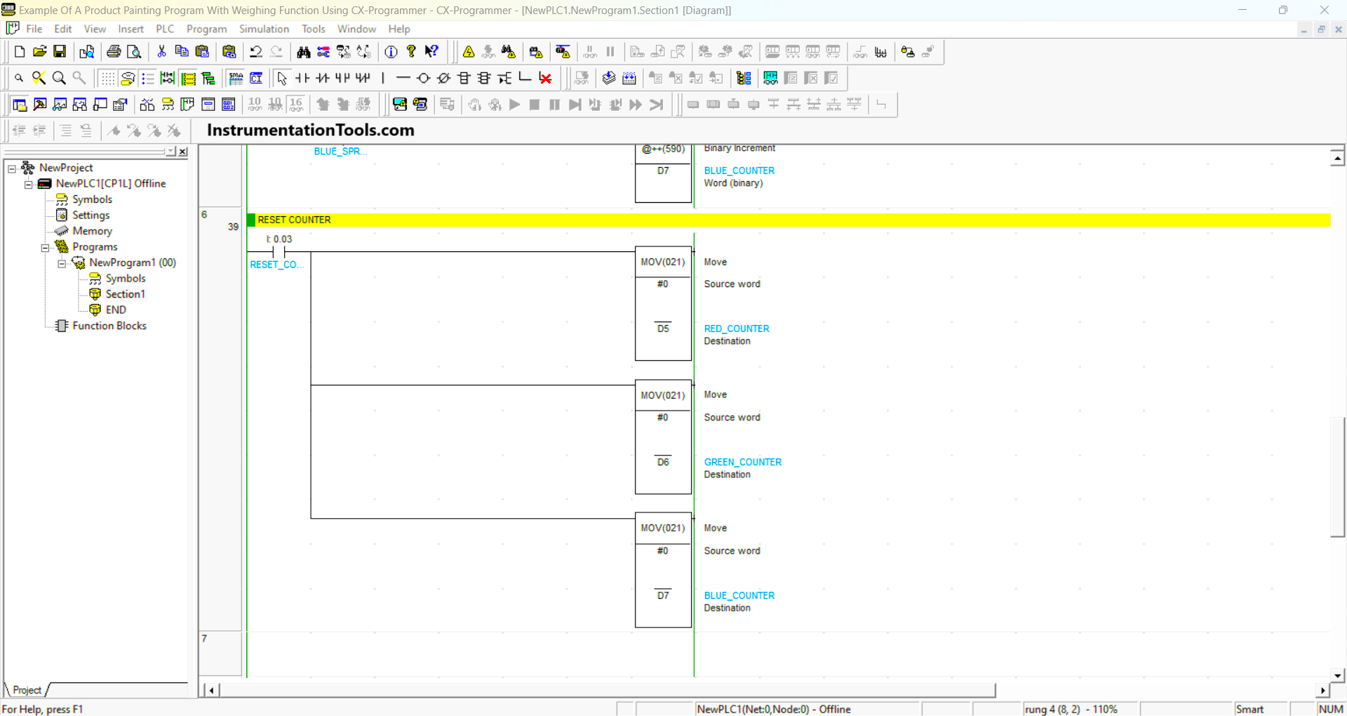
RUNG 6 (RESET COUNTER)
In this rung, if the RESET_COUNTER (0.03) button is pressed, the data in memory words RED_COUNTER (D5), GREEN_COUNTER (D6), and BLUE_COUNTER (D7) will be Reset to zero “0”.
Read Next:
- Belt Conveyor Weighing System
- Schneider Electric PLC Timer Problem
- Omron PLC Logic for Washing Machine
- Configure PID Controller in Schneider PLC
- Automate Batch Mixing with Repeated Cycle