Inst ToolsInst ToolsInst Tools
  • Ask
  • Courses
  • Videos
  • Q & A
    • Interview
      • Instrumentation
      • Electronics
      • Electrical
      • Practical Questions
    • MCQ
      • Instrumentation MCQ
      • Electrical MCQ
      • Electronics MCQ
      • Control Systems MCQ
      • Analog Electronics MCQ
      • Digital Electronics MCQ
      • Power Electronics MCQ
      • Microprocessor MCQ
      • Multiple Choice Questions
  • EE
    • Electronics
      • Electronics Q & A
      • Electronic Basics
      • Electronic Devices & Circuits
      • Electronics Animation
      • Digital Electronics
    • Electrical
      • Electrical Basics
      • Electrical Q & A
      • Power Electronics
      • Electrical Machines
      • Electrical Animation
      • Power Systems
      • Switchgear & Protection
      • Transmission & Distribution
  • Measure
    • Control Valves
    • Calibration
    • Temperature
    • Pressure
    • Flow
    • Level
    • Analyzers
    • Switches
    • Vibration
    • Solenoid Valve
  • Control
    • PLC Tutorials
    • Control Systems
    • Safety Instrumented System (SIS)
    • Communication
    • Fire & Gas System
  • More
    • Design
    • Tools
    • Animation
    • Basics
    • Formulas
    • Standards
    • TextBooks
    • Common
    • Software
    • Excel Tools
    • Erection & Commissioning
    • Process Fundamentals
    • Videos
    • Books
Search
All rights reserved. Reproduction in whole or in part without written permission is prohibited.
Reading: Motor Controllers
Share
Notification Show More
Font ResizerAa
Inst ToolsInst Tools
Font ResizerAa
  • Courses
  • PLC Tutorials
  • Control Systems
Search
  • Ask
  • Courses
  • Videos
  • Q & A
    • Interview
    • MCQ
  • EE
    • Electronics
    • Electrical
  • Measure
    • Control Valves
    • Calibration
    • Temperature
    • Pressure
    • Flow
    • Level
    • Analyzers
    • Switches
    • Vibration
    • Solenoid Valve
  • Control
    • PLC Tutorials
    • Control Systems
    • Safety Instrumented System (SIS)
    • Communication
    • Fire & Gas System
  • More
    • Design
    • Tools
    • Animation
    • Basics
    • Formulas
    • Standards
    • TextBooks
    • Common
    • Software
    • Excel Tools
    • Erection & Commissioning
    • Process Fundamentals
    • Videos
    • Books
Follow US
All rights reserved. Reproduction in whole or in part without written permission is prohibited.
Inst Tools > Blog > Electrical Theory > Motor Controllers

Motor Controllers

Last updated: September 27, 2018 2:18 pm
Editorial Staff
Electrical Theory
No Comments
Share
4 Min Read
SHARE

Motor controllers range from a simple toggle switch to a complex system using solenoids, relays, and timers. The basic functions of a motor controller are to control and protect the operation of a motor.

Contents
Motor ControllersManual ControllersMagnetic Controller

Motor Controllers

Motor controllers range from a simple toggle switch to a complex system using solenoids, relays, and timers. The basic functions of a motor controller are to control and protect the operation of a motor. This includes starting and stopping the motor, and protecting the motor from overcurrent, undervoltage, and overheating conditions that would cause damage to the motor.

There are two basic categories of motor controllers:

  1. the manual controller and
  2. the magnetic controller.

Manual Controllers

A manual controller, illustrated by Figure 1, is a controller whose contact assembly is operated by mechanical linkage from a toggle-type handle or a pushbutton arrangement. The controller is operated by hand.

The manual controller is provided with thermal and direct-acting overload units to protect the motor from overload conditions. The manual controller is basically an “ON-OFF” switch with overload protection.

Manual controllers are normally used on small loads such as machine tools, fans, blowers, pumps, and compressors. These types of controllers are simple, and they provide quiet operation. The contacts are closed simply by moving the handle to the “ON” position or pushing the START button. They will remain closed until the handle is moved to the “OFF” position or the STOP button is pushed. The contacts will also open if the thermal overload trips.

Manual controllers do NOT provide low voltage protection or low voltage release. When power fails, the manual controller contacts remain closed, and the motor will restart when power is restored. This feature is highly desirable for small loads because operator action is not needed to restart the small loads in a facility; however, it is undesirable for larger loads because it could cause a hazard to equipment and personnel.

Single Phase Motor Manual Controller

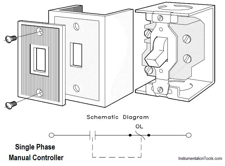
Figure 1 : Single Phase Manual Controller

Magnetic Controller

A large percentage of controller applications require that the controller be operated from a remote location or operate automatically in response to control signals. As discussed, manual controllers cannot provide this type of control; therefore, magnetic controllers are necessary.

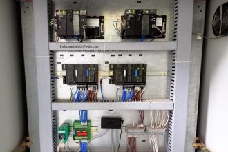
Basic operations using a magnetic controller, such as the closing of switches or contacts, are performed by magnetic contactors. A magnetic controller is one that will automatically perform all operations in the proper sequence after the closure of a master switch. The master switch (for example, float switch, pressure switch, or thermostat) is frequently operated automatically. But in some cases, such as pushbuttons, drum switches, or knife switches, the master switch is manually operated. Figure 2 shows a typical magnetic controller and its component parts.

Three Phase Magnetic Controller

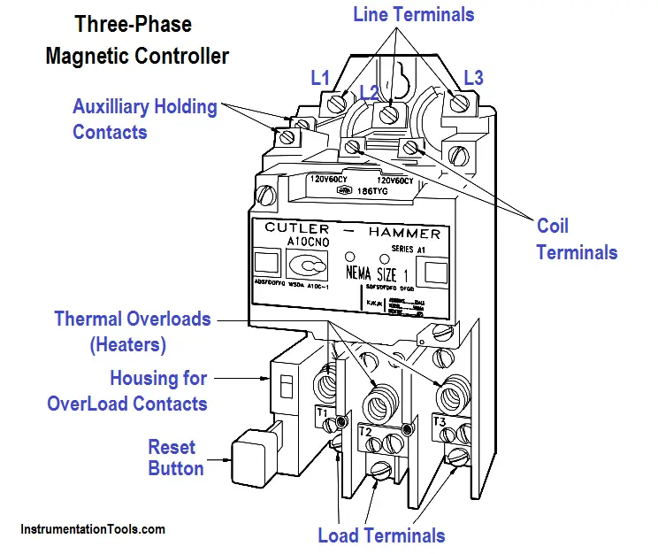
Figure 2 : Typical Three-Phase Magnetic Controller

Magnetic Controller Circuit

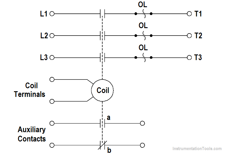
A magnetic contactor (Figure 2) is a device operated by an electromagnet.

Magnetic Contactor Assembly

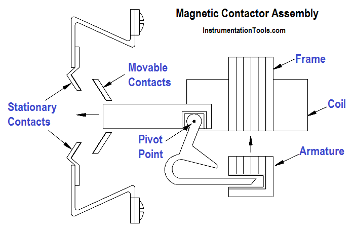
Figure 3 : Magnetic Contactor Assembly

The magnetic contactor consists of an electromagnet and a movable iron armature on which movable and stationary contacts are mounted. When there is no current flow through the electromagnetic coil, the armature is held away by a spring. When the coil is energized, the electromagnet attracts the armature and closes the electrical contacts.

Overload devices are incorporated into magnetic controllers. These overload devices protect the motor from overcurrent conditions that would be extremely harmful. There are many types and forms of overload devices. The following types of overload devices are commonly used in motor-control equipment.

  • Fuses
  • Thermal overloads
  • Magnetic overloads

The thermal overload device is shown in Figure 2.

Don't Miss Our Updates
Be the first to get exclusive content straight to your email.
We promise not to spam you. You can unsubscribe at any time.
Invalid email address
You've successfully subscribed !
AC Generation Analysis : Effective Values, Phase Angle and Frequency
Single Phase Power Wiring Schemes
Power Triangle
Calculate Power in Parallel RCL Circuit
Reading Electrical Schematics
Share This Article
Facebook Whatsapp Whatsapp LinkedIn Copy Link
Share
Leave a Comment

Leave a Reply Cancel reply

Your email address will not be published. Required fields are marked *

Stay Connected

128.3kFollowersLike
69.1kFollowersFollow
208kSubscribersSubscribe
38kFollowersFollow

Categories

Recent Comments

  • Guifty Shimica on Top Non-PLC Certification Courses for Automation Professionals
  • Guifty Shimica on Top Non-PLC Certification Courses for Automation Professionals
  • MIHARITSOA Aina Sitraka on Top Non-PLC Certification Courses for Automation Professionals
  • Vaishnavi on Free Instrumentation Course for Trainee Engineers

Related Articles

AC to DC Conversion with a Commutator

DC Machines Terminology

Three-Phase Wye Wiring System

4-Wire, Three-Phase Wye Wiring System

Resistor Y and Delta Network Calculation

Y and Delta Resistor Network Calculations

Synchronous Motor Principle

Synchronous Motors

Developing a Sine-Wave Voltage of Motor

AC Generation

induction motor torque versus speed

Induction Motor Torque Versus Slip

Transformer Efficiency and Loses Formula

Transformer Losses and Efficiency

Parallel Open Circuit Fault

Parallel Open Circuit Faults

More Articles

example-of-KCL

What is Kirchhoff’s Current Law

A Large Gate Valve Failed Motorized Operation

A Large Gate Valve’s Failed Motorized Operation

Analytical Instrumentation Engineering Projects

Top 100 Analytical Instrumentation Engineering Projects

Thermocouple Voltage Curves

What are the Thermocouple Applications?

Functions of Rupture Disc

Why is a Rupture Disc Required? – Functions & Selections

RFID Technology in Industrial Automation

RFID Technology in Industrial Automation

mass flowmeters

What is a Thermal Flow Meter?

Under and Over-Capacity Control Valve

Under and Over-Capacity Control Valve Pose Poor Controllability

Follow US
All rights reserved. Reproduction in whole or in part without written permission is prohibited.
Welcome Back!

Sign in to your account

Username or Email Address
Password

Lost your password?